yes you should, but remember that the primary and the secondary must be in phase, to make test always use a ligtbulb in series with the mains for your test if connection is ok the lightbulb will not ligt up if your connection is out of phase (reversed ) the light will go bright
So, you say that it's possible that the colours of the primaries on the two transformer could be inverted?!
(my transformers is single primary / single secondary)
and so could happend that in the moment I matched the wires of the secoundaries (live with live and ground with ground) they could go in short?
Ehi, this is extremely dangerous!
What kind of mad engineer can make a mistake like this? !
..
(my transformers is single primary / single secondary)
and so could happend that in the moment I matched the wires of the secoundaries (live with live and ground with ground) they could go in short?
Ehi, this is extremely dangerous!
What kind of mad engineer can make a mistake like this? !
..
Ciao! Yes it can happen. But it is a rare event. Try the lightbulb trick in series with the primary leads. It senses the short and protect the transformers in case of serious trouble. In general if the 2 transformers are identical, just connect togheter the wires of the same color...
But why are you doing this? Get a cheap 225VA toroid and you'll thank yourself later... (I assume you are talking about EI transformers)
But why are you doing this? Get a cheap 225VA toroid and you'll thank yourself later... (I assume you are talking about EI transformers)
I've bought these 4 trasformers for just 15€, they are preatty heavy and well made, I bought 4 trasformers to create a two-rails psu like ones suggested by dejan Vaselinovich in his tnt articules...but since I search a pure class A amp, I 've decided to built a Zen amp (single ended) I think that I can't use a two rail psu in a single ended amp so I've decided to connct them parallel to got a nice psu for a 15-20W final mono.
If you could suggest a way to implement a two rail psu in S.E. amp make me know.
Cheers,
Domenico
If you could suggest a way to implement a two rail psu in S.E. amp make me know.
Cheers,
Domenico
Guys,
Unless the trafo's are made to very high tolerances, they may not match. You need to connect all wires in paralell, then open one connection at one end of the secondaries and measure the voltage difference. It should be less than 0.05v (5mV) anything more and your transformer will drive the other and cook it.... use a 20-40 watt bulb to check.
Unless the trafo's are made to very high tolerances, they may not match. You need to connect all wires in paralell, then open one connection at one end of the secondaries and measure the voltage difference. It should be less than 0.05v (5mV) anything more and your transformer will drive the other and cook it.... use a 20-40 watt bulb to check.
")

primaries should be in parallel and connected to mains at nominal voltage if you want to get the maximal power period..
then secondaries should be in series if you want to double the output voltage and get nominal current. In this type of connection a ""reversed''' connection will give no voltage at all
the secondarie should be in parallel if you want the nominal voltge and double the current.In this type of connection a ''reversed '' connection will short circuit the transformer and must be avoided, this is why you need to test with a ligtbulb.
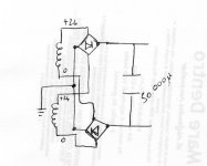
Hi, audiofan. what you say was clear to me...my last question is above the use of the bridge rectifiers in the way shown in the picture, this should let me avoid the problem of little difference in voltage between the secondaries... 0.5mv or so... this idea is of dejan vaselinovich (check its articule on www.TNT-audio.com)
Hi,
Domenico
Hi,
Domenico
Ihave check the ''psu2.jpg ''attachement and if I read it correctly it is a hoak........... it does not work.
I you follow the circuit from the ground point on the upper bridge, throug the diode ( top left) in this bridge, the upper transformer winding,the diode in the lower bridge (top left) you go to ground again, short circuit guarantied, bye....... the fuse or bye...... the transformer.....if no fuse in the circuit.
I you follow the circuit from the ground point on the upper bridge, throug the diode ( top left) in this bridge, the upper transformer winding,the diode in the lower bridge (top left) you go to ground again, short circuit guarantied, bye....... the fuse or bye...... the transformer.....if no fuse in the circuit.
I find by myself the problem in the project! Just before you post the reply!! What stupid thing!
So I redraw the psu in this way did you think that the two diodes par rail should help with that 0.5mv of difference?
Wich diode I should use for best performance?
So I redraw the psu in this way did you think that the two diodes par rail should help with that 0.5mv of difference?
Wich diode I should use for best performance?
Attachments
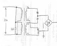
this will not work each transfo in use in series with a pair of diode and will use only half the ac signal
if you have a pair of similar tranfo same brand same model same batch you may wire them in parallel and this is it ( with correct phase )
if you want someting for the ubalance wire each transfo to a full wave bridge the usual way ant connect in parallel the output of the bridge this will work
if you have a pair of similar tranfo same brand same model same batch you may wire them in parallel and this is it ( with correct phase )
if you want someting for the ubalance wire each transfo to a full wave bridge the usual way ant connect in parallel the output of the bridge this will work
This is a schematic for a high current 12V supply,so you can kind of ignore that part of it..But,It Does show the parallel-bridge setup.
http://www.users.qwest.net/~ptaylor/Electronics/MOTpowersupply/HighCurrentSupplySchema.jpg
You would parallel 2 transformers and 2 bridges for each rail of your split supply.So you'd have one pair of transformers and bridges for the +V rail,and another pair of trannies and bridges for the -V rail.
Hope that helps out a bit..
- Status
- This old topic is closed. If you want to reopen this topic, contact a moderator using the "Report Post" button.
- Home
- Amplifiers
- Solid State
- PSU transformer question