Hey
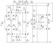
Here is my 25Cents for a circuit with folded Back cascode coupled transistors.
All transistors are 2SC2240(npn) and 2SA970(pnp)
except Q17-18 are 2SC4159 and 2SA1606.
The supply (+-10V comming from a LCAudio shuntreg)
The circuit is intended for a Highend preamplifier.
The gain is 2times (6dB)
Please make some comments about my circuits and your opinien to make it to the top.
Thanks
Best regards
Attachments
first impresions:
1. I don't know how lm339 behaves, but check if its output reaches close to rail voltage (10...0...-10 I guess)
2. I haven't calculated the poles, but am a little suspicious about C1 and stability issues- do you really need it?
3. It is global feedback free, so check if distortion is small enough
4. It's demon fast- think how to avoid RF interference, consider input C to the ground or paralel to R8, just several picoFarads
5. If above are pointless, then... GOOD WORK! Listen ihow it sounds and enjoy.
cheers
Balanced out?
Thanks")
Does someone know how to connect two DC servos, if i want to make it balanced?
Imagine I also take out off the left Collektor in both differentiale amplifiers, so i have a + and a - output.
1. its working fine as it is..
2. C1 prevents High freqency issues in the circuits.
Maybe it commes from Q15-16 when it´s try to hold down Q17-18? noted it with scope.
3. The distortion is 0.08% with 10Vpp with RL =100R and clipping with 15Vpp.
4. Good point there-> I think a resistor in serie with a capacitor about 56pF in parallel with R9 (and R10) should do the job, so you prevent RF in the circuits?
Best regards
Thanks
Does someone know how to connect two DC servos, if i want to make it balanced?
Imagine I also take out off the left Collektor in both differentiale amplifiers, so i have a + and a - output.
1. its working fine as it is..
2. C1 prevents High freqency issues in the circuits.
Maybe it commes from Q15-16 when it´s try to hold down Q17-18? noted it with scope.
3. The distortion is 0.08% with 10Vpp with RL =100R and clipping with 15Vpp.
4. Good point there-> I think a resistor in serie with a capacitor about 56pF in parallel with R9 (and R10) should do the job, so you prevent RF in the circuits?
Best regards
Hey Anatech
My idea with Q15 and 16 was to make a CCS with Q17-18, then I could use 2SC2240 2SA970 (for Q15-16) and did not have to couple Q15-18 together with Q17-18.
Q15-16 do also make a shortcircuit protectection.
Butt it´s not needed now with diamond buffer??
Would it be better to lower R20,21 to 100R and R22-23 to 5ohm?
I forgot to say that i measured the distortion fromm 100Hz to 20Khz (0.08%) with this:
PC
Soundcard Soundblaster Audigy 2
Software : Oscillometer 5.07
Low distortion generator.
How about the resistors R3-R8? does anyone have a better solution to values?
Best regards
The LM339 IC isn't an op-amp, it's a comparator thus it's designed with response times in mind and ignoring stability issues. There are no guarantees about comparator stability but be sure that it won't be unity-gain stable, it will oscillate like crazy when negative feedback is applied
The LM339 isn't unity gain stable unless you make a very slow output stage but remember also that the servo is injecting a small amount of audio signals back into the amp, therefore the servo have to have good audio properties to 100-1000 Hz depending where you place your target.
You must also take into account the supply voltage of the servo and desired output voltage.
Why don't you let the servo go to the inverting input like the rest of us would do?
You must also take into account the supply voltage of the servo and desired output voltage.
Why don't you let the servo go to the inverting input like the rest of us would do?
Hey.
(Peranders) I won´t send the servo back to the inventing input, because the circuit are also intended to be used balanced and in my cd player, which gives a balanced voltage out from the dac.
About slewrate it´s not so fast as Peranders, butt I measure it tonight again.
Anyone having ideas to make it faster and to lower the distortion?
How good is a capacitor in 100uF to decouple the supply for freqencies higher than 100Khz?
I´m asking because the supply is comming from a Shunt reg which impedance and Ft will be about 0.01R from DC to 400Khz.
And I try to make the circuit so good (Powersupply) so the sound will be free as possible from "capacitorsound"
Thanks for all
Kim
My limited experience with a comparator, LM339, says that the output will be binary, i.e. a square wave with the same period as the input signa. In this case "low" is ground/0V and "high" will be just a smodgen below the rail voltage (or whatever feeds Vcc). If the feedback cap is big enough (1,000uF ?) the square wave will become a sine again but with a DC offset.
Is this what's intended here?
Is this what's intended here?
I have a broader question/concern about DC servos:
Some musical signals may naturally have brief (a few cycles of) DC offset in them even if the average offset over a longer period of time averages out to zero offset. In such a case, doesn't a DC servo introduce distortion (in the broad sense of: Output .NE. Input*A, not just harmonics)? Following that logic, is a simple adjustment that achieves quiecent zero offset not only all that is needed but all that is desired?
These are not Socratic questions -- I'm really puzzeled on this metter.
Correction to my comment about the servo. Now that I see it is an opamp that removes considerable confusion including that my use until now of comparators was always with a single supply. With a split supply it would swing both ways.
It is now clear to me wat the purpose is.
My broader question about DC servos when the input signal containds an offset still stands.
It is now clear to me wat the purpose is.
My broader question about DC servos when the input signal containds an offset still stands.
PSSR
After a quick look and some napkin calculations:
current through r12 depends on power supply - and is also the ref for the cb stages Q2 and Q7 - leading to poor PSRR I would think. My suggestion would be a FET current source instead of R12 - of course this might ruin something else.
Still trying to understand exactly how the output buffer will behave. My spice is down and don't really have time to think to hard about this stage. Lets see about Iq= 70mA, drivers about 3mA ...
Using R18/19 as current sources in output stage(instead of a ccs) will degrade the PSRR.
This will also lead to varying current though them with output voltage and therefore the voltage across R20/21 and effecting the voltage at the base of the outputs. Good or bad ? I'm still trying to get it clear in my head. Certainly not the usual arrangement for this topology.
So maybe a better thing to write would be a question: What is the output voltage and distortion at the input to the buffer? Or put a different way what is the gain and distortion of the buffer?
Bill
Hello
I make it first with two resistors instead off two CCS in the outputstage,and then with two CCS and so on to see (hear) measure every change I made in the circuit.
How much improvement in PSU/ sound will a fet CCS give to the circuit instead off R12?
The distortion at the base off Q7 and Q12 is:
12Vpp = 0.08% 20Hz to 20Khz.
14Vpp =0.14% 20Hz to 20KHz
The amplitude is clipping at 15Vpp
12Vpp RL =100R Output off buffer Q17-18 = 0.3% (10Vpp 0.1%)
Any idea to optimize the distortion in the circuit before Q7 and Q12?
Best regards
Hi kimschips,
You have a diamond buffer plus extra parts. My work with these is promising. You don't want the outputs to be current sources. They aren't anyway in common emitter.
A diamond buffer with coupled transistors is very stable. The bias changes very little from cold start to running with a 30°C rise as long as all transistors are thermally coupled. Set and forget. R20,21 and R22,23 set the bias current. This unloads the vas from the outside world pretty much. You can even take your feedback from the input of your buffer, eliminating some phase shift. Try it.
-Chris
kimschips said:Hello
How much improvement in PSU/ sound will a fet CCS give to the circuit instead off R12?
Any idea to optimize the distortion in the circuit before Q7 and Q12?
Best regards
Without building I have no idea about sound or measurement changes by adding a CCS - but it would not be hard to do, and listen and measure, and listen.
Optimizing - if you have a differential input on your thd analyser I would suggest looking across R3/4 and measure distortion, to try to determine which stage is creating the distortion - assuming of course that one is not trying to pre distort the signal to cancel distortion in a later stage (that idea always seems a bit dicey to me, since once created it seems that it may be hard "to put the cat back in the bag")
You probably have checked out Curl's cascode topology, if not you might want to (http://marklev.com/ not the preamp but his power amp JC-3). I am not suggesting that you use it, I have never played with it though I have listened to some of his amps - too long ago to make any useful comments. He used NF.
I 'm not sure I've seen your topology before - though I'm hardly an expert - nice to see something a little different. I designed a circuit awhile ago which 'injected' a current into the emmiter resister of a current source and thereby altered Ic, I have not built it yet, but it did look good in SPICE for whatever that's worth (maybe not much since I was using pretty generic models - SPICE is nice to play with and make sure that you have not made silly mistakes but I believe in breadboards!).
... and now back to my design - which as my students (I'm math and science teacher) say "is exactly the same, except different" !!! actually quite different, but presently zero global feedback as well
Have fun, listen, measure and listen
Bill
oh - and I agree about the diamond buffer - loose the extra Transistors, reduce those 220 resistors by as much as possible - I have played with these - hard to get zero offset, but they can be stable and quite linear.
And don't forget that its your design, so please ignore anything I suggest if its not your liking.
Got to stop typing and thinking, work to do!
Hello.
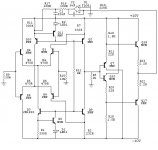
I have now read your messages and changed my schematig.
Thanks for your input and links.
New distortion numbers measured between 20Hz to 20Khz:
12Vpp With RL= 100R with 0.14% THD
10Vpp into 100R with 0.08% THD
10Vpp into 50R with 0.3% THD
Risetime is about 250nS
I have now read your messages and changed my schematig.
Thanks for your input and links.
New distortion numbers measured between 20Hz to 20Khz:
12Vpp With RL= 100R with 0.14% THD
10Vpp into 100R with 0.08% THD
10Vpp into 50R with 0.3% THD
Risetime is about 250nS
Attachments
It's more accurate to call it low frequency AC, not DC. Yes, removing it does prevent the amp from achieving the ideal of being pure gain, but that isn't always desirable. Any signal of a few Hz that manages to make it this far through any DC blocking capacitors at any point in the recording/reproduction chain will be of no sonic interest since the speakers will completely fail to reproduce them. In fact trying to reproduce them may cause more distortion in itself.sam9 said:I have a broader question/concern about DC servos:
Some musical signals may naturally have brief (a few cycles of) DC offset in them even if the average offset over a longer period of time averages out to zero offset. In such a case, doesn't a DC servo introduce distortion (in the broad sense of: Output .NE. Input*A, not just harmonics)? Following that logic, is a simple adjustment that achieves quiecent zero offset not only all that is needed but all that is desired?
These are not Socratic questions -- I'm really puzzeled on this metter.
Hi kimschips,
Increase the value of R8, try 47K to start. Your THD numbers may drop. I find DC offset with 100K normally sits within 40mV of ground. Not bad. Where are you taking your feedback from?
Mr. Evil,
So true. I wish more people would think of what goes on outside the amp for a change.
-Chris
Increase the value of R8, try 47K to start. Your THD numbers may drop. I find DC offset with 100K normally sits within 40mV of ground. Not bad. Where are you taking your feedback from?
Mr. Evil,
So true. I wish more people would think of what goes on outside the amp for a change.
-Chris
- Status
- This old topic is closed. If you want to reopen this topic, contact a moderator using the "Report Post" button.
- Home
- Amplifiers
- Solid State
- Critics needed