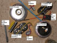
hi all, this is my second power amp that i have ever built, and would like some comments on the PSU configuration (see picture)…
it is based on the 175w Jaycar modules Jaycar module
the PSU and amplifier are going to be in separate boxes, (to save space and ease portability)
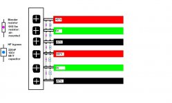
my PSU will have two outputs of +/- 57V and two earths that will feed each of the two 175W boards.
the toroidals are 300VA with 40V windings, the caps are some stubby 15'000uF 80V ones i stumbled across, the regs are big 35A ones and the filtering will be mostly 0.1uF caps on the power rails.
it will be mounted on a 4mm thick 280x220 board.
does this look OK?
the 6 way terminal block will have 8ga leads to the amplifier unit of a max of 300mm length.
i am still trying to work out if i can have a safety feature on the flying 57v leads that only allows electricity to flow if it is connected at the amplifier end...
it is based on the 175w Jaycar modules Jaycar module
the PSU and amplifier are going to be in separate boxes, (to save space and ease portability)
my PSU will have two outputs of +/- 57V and two earths that will feed each of the two 175W boards.
the toroidals are 300VA with 40V windings, the caps are some stubby 15'000uF 80V ones i stumbled across, the regs are big 35A ones and the filtering will be mostly 0.1uF caps on the power rails.
it will be mounted on a 4mm thick 280x220 board.
does this look OK?
the 6 way terminal block will have 8ga leads to the amplifier unit of a max of 300mm length.
i am still trying to work out if i can have a safety feature on the flying 57v leads that only allows electricity to flow if it is connected at the amplifier end...
Attachments
yeah, the 'bridge rectifiers' (sorry!!!) will be mounted using dielectric grease to the 4mm thick 280x220mm aluminium base plate,
i hope this is enough of a sink for heat")
'star earth' will be somewhere in the centre, i will have every earth and 0v line connected there, is that right?
the reason for the 'spread-out' transformers was basically due to aesthetics (it will have a perspex cover)
i did not think there would be any negative from this? i thought it would be better to keep both sides seperate...?
plus i want to keep it low profile (again for aethetics )
so you guys cant see any negatives with the layout?
thanks for the input
i hope this is enough of a sink for heat
'star earth' will be somewhere in the centre, i will have every earth and 0v line connected there, is that right?
the reason for the 'spread-out' transformers was basically due to aesthetics (it will have a perspex cover)
i did not think there would be any negative from this? i thought it would be better to keep both sides seperate...?
plus i want to keep it low profile (again for aethetics
)so you guys cant see any negatives with the layout?
thanks for the input
costiss said:negative: non symmetrical power traces to each channel.. some advice: pay attention to your contacts..
but everything will be symmetrical? what are the non-symmetrical power traces?
i plan on hard soldering everything, are these the contacts that you might mean?

Hi,
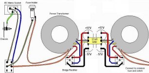
the two rectifiers should connect together to form a 0volt point. There are very large pulse currents running between the +caps and -caps to 0v do NOT take separate wires from each cap bank to ground. Instead take one wire from 0v to star ground, this isolates the dirty ground from the clean ground. When connecting the power amp to the PSU the dirty returns from all the onboard decoupling caps must be separate from the clean grounds to the signal returns.
Q1. do we need two ground returns from power amp to PSU, dirty and clean? or can they be tied at a local star ground?
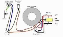
this is the circut diagram i followed for one channel of the power supply.
each of the two channels capacitor 0V's were going to join with the other side's 0v line at the star earth.
or should i have 1 star earth for each channel? is that what you mean?
i hope the pictures help!
each of the two channels capacitor 0V's were going to join with the other side's 0v line at the star earth.
or should i have 1 star earth for each channel? is that what you mean?
i hope the pictures help!
Attachments
Hi,
although I would connect the fuse directly to the mains connector (as the switch is already a part that could fail), I see no problem so far.
However, the interesting part is to see how two of them go in one enclosure, sharing a single mains connection and a common output connector. It's clear how it should look in theory, but 'correctness' can only be judged by your actual mouting and connections.
Could you apply your last picture to the photo of the parts (or draw another one with both of the supplies)?
Cheers,
Sebastian.
is this what you are asking for?
the 240v IEC socket has a fuse and a switch, so the 240V comes straight from the socket.
this is the only place where each channel is touching, they are completely independent from there on.
the filtered power output goes to a 6 way terminal board to attach to the ampifier, so there are two sets of seperate 57-0-57 outputs.
when you talk about 'correctness' fo mounting, do you mean keeping lenghts of wire perfectly equal - what else do you need to ensure proper mounting?
Attachments
for anyone who has found this thread by searching if they are looking for power supply design information, i have just found an excellent site that explained a few new things for me:
http://www.zero-distortion.com/techno/powersupply/powersi.htm
it is from this site: http://www.zero-distortion.com/start.htm
hope this helps (it has certainly helped me )
http://www.zero-distortion.com/techno/powersupply/powersi.htm
it is from this site: http://www.zero-distortion.com/start.htm
hope this helps (it has certainly helped me
)Hi tinkerbell,
Yes, very good, thanks.
I see, that's what I was unsure about.
No, I'm talking about safety (first), function (second) and quality (third).
Absolutely equal wire length isn't important. Just make sure it's fixed well (not just hung off the terminals or soldering joints) and probably twisted (+ wire with - wire, 0V perhaps separately in parallel).
I've found just two things to think about:
1. You probably want to have a connection between circuit ground and protective earth somewhere, because you never know what touchable metal parts your amplifier will have in the end (or what amplifiers you will connect the supply to in the future). I'd recommend to wire PE to the output terminal, too. BTW, any externally touchable metal parts of the supply enclosure itself have to be connected to PE, too (but preferably not on a screw terminal but a separate point, i.e. directly on a metal front plate...).
2. Don't forget to 'define' a ground star point in the amplifier enclosure. You'll need a common star point (where both channels join their grounds) only if you have a common signal source in the amplifier enclosure that has a connection to PE (or another common ground, i.e. input wiring), because this would then connect the grounds of the amp channels in loops. If everything is kept strictly separated, you could also use the 0V terminal inputs of the amplifier enclosure, but I would do it on the amplifier boards.
You mean like shutting down the output voltage when no amp is connected? This is only possible with either a swith or complex circuitry in both the supply and the amplifier enclosures.
An electronic circuit could probably measure output load and swith off below a certain threshold (e.g. when the load resistance/impedance goes up).
But how would you make it switch back on? If it senses for a reduced load resistance/impedance, wouldn't it also switch on if you accidentally shorted the outputs?
The common way to get around this problem is using isolated connectors...
What a nice coincidence, I had also just re-read the article by Dejan V. Veselinovic the other day.
Sebastian.
tinkerbell said:is this what you are asking for?
Yes, very good, thanks.
the 240v IEC socket has a fuse and a switch [...], they are completely independent from there on
I see, that's what I was unsure about.
when you talk about 'correctness' fo mounting, do you mean keeping lenghts of wire perfectly equal - what else do you need to ensure proper mounting?
No, I'm talking about safety (first), function (second) and quality (third).Absolutely equal wire length isn't important. Just make sure it's fixed well (not just hung off the terminals or soldering joints) and probably twisted (+ wire with - wire, 0V perhaps separately in parallel).
I've found just two things to think about:
1. You probably want to have a connection between circuit ground and protective earth somewhere, because you never know what touchable metal parts your amplifier will have in the end (or what amplifiers you will connect the supply to in the future). I'd recommend to wire PE to the output terminal, too. BTW, any externally touchable metal parts of the supply enclosure itself have to be connected to PE, too (but preferably not on a screw terminal but a separate point, i.e. directly on a metal front plate...).
2. Don't forget to 'define' a ground star point in the amplifier enclosure. You'll need a common star point (where both channels join their grounds) only if you have a common signal source in the amplifier enclosure that has a connection to PE (or another common ground, i.e. input wiring), because this would then connect the grounds of the amp channels in loops. If everything is kept strictly separated, you could also use the 0V terminal inputs of the amplifier enclosure, but I would do it on the amplifier boards.
i am still trying to work out if i can have a safety feature on the flying 57v leads that only allows electricity to flow if it is connected at the amplifier end...
You mean like shutting down the output voltage when no amp is connected? This is only possible with either a swith or complex circuitry in both the supply and the amplifier enclosures.
An electronic circuit could probably measure output load and swith off below a certain threshold (e.g. when the load resistance/impedance goes up).
But how would you make it switch back on? If it senses for a reduced load resistance/impedance, wouldn't it also switch on if you accidentally shorted the outputs?
The common way to get around this problem is using isolated connectors...
i have just found an excellent site that explained a few new things for me
What a nice coincidence, I had also just re-read the article by Dejan V. Veselinovic the other day.
Sebastian.
i was thinking a 'mechanical' system, along the lines of a magnetic reed switch or similar? would this be viable?
it would have to sit on the amplifier side, and have a 'trigger wire' running back to a relay on the PSU side. i am not sure it is going to be a major concern, i think i will just fuse all the 57-0-57 lines in the PSU, and make sure the unit is off when connecting - my only reason for a 'fail-safe' protection is for other users, which at the moment is nil.
what are 'isolated' connectors? did you mean insulated? or is isolated a different meaning?
sek, you also mention defining a star ground in the amplifier section.
the amplifier PCB is already 'star grounded' and has the 0V point, speaker out and signal in at the same point on the circut.
is this enough - i had assumed that this was the amplifiers 'star earth' (since it looks like a star!)
additionally, is there really need for a PE connection in the amp. section if the only point of power contact is wth the PCB, with the aluminium heatsinks and base plate isolated from any current?
NEW QUESTION:
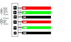
for the HF filtering and bleed resistors, can i mount them on the power out terminal block about 10cm down the wire from the caps?
like in the attached picture?
it would have to sit on the amplifier side, and have a 'trigger wire' running back to a relay on the PSU side. i am not sure it is going to be a major concern, i think i will just fuse all the 57-0-57 lines in the PSU, and make sure the unit is off when connecting - my only reason for a 'fail-safe' protection is for other users, which at the moment is nil.
what are 'isolated' connectors? did you mean insulated? or is isolated a different meaning?
sek, you also mention defining a star ground in the amplifier section.
the amplifier PCB is already 'star grounded' and has the 0V point, speaker out and signal in at the same point on the circut.
is this enough - i had assumed that this was the amplifiers 'star earth' (since it looks like a star!)
additionally, is there really need for a PE connection in the amp. section if the only point of power contact is wth the PCB, with the aluminium heatsinks and base plate isolated from any current?
NEW QUESTION:
for the HF filtering and bleed resistors, can i mount them on the power out terminal block about 10cm down the wire from the caps?
like in the attached picture?
Attachments
Hi,
sorry for the late response; I've been off the net for a couple of days.
How is your progress, any new pictures?
Then I think it is an unneccessary effort (work to do, parts that cost money and could fail, etc.) ...
You are right, I was talking about insulation, sorry.
This is good, but...
... that depends.
You plan to build two PSUs, which makes me think you want to have two amplifier boards, each connected to one PSU.
If you connect a stereo source (which has a common ground for both channels), the two amplifier sections now share their ground. If you have just one ground connection elsewhere, you could introduce hum.
No, not really. I just mentioned it, because if you can't get around multiple ground loop connections (for whatever reason), it helps to have the option to form a "real" star ground (where all ground wires meet). But as long as you don't expect problems with your wiring, there's no need for a PE safety measure in the amp section (because there are only "low" voltages present in the amp enclosure).
To sum this up: your plan looks good so far, go for it.
If I'm not mistaken, a resistor of 6k8 (having 57V across it) conducts >8.4mA and thus burns >0.5W constantly. I don't think they will become too warm (as you have specified 5W types) and there's no need to put them into a special location.
You could even go for a lower power type or a lower resistance (which would of course waste more power...), and it's okay to mount them at the terminals (standing off, not touching plastics or wood, of course).
But wait a minute, what's the bleeder/filter between -57V of the upper and +57V of the lower supply for? This could certainly create problems and is not neccessary.
It's a rule of thumb that a bleeder resistor should be selected so that the output voltage is low enough (for everyone to touch safely and probably for the capacitors to survive a short) after about five time constants. R*C for your design is ca. 6800Ohm * 0.015F = 102s (right???). This would sound like 8min to reach only a couple of volts left, but wasting more power has other drawbacks, e.g. more heat inside the enclosure...
Ciao,
Sebastian.
sorry for the late response; I've been off the net for a couple of days.
How is your progress,
any new pictures?tinkerbell said:my only reason for a 'fail-safe' protection is for other users, which at the moment is nil.
Then I think it is an unneccessary effort (work to do, parts that cost money and could fail, etc.) ...
what are 'isolated' connectors? did you mean insulated? or is isolated a different meaning?
You are right, I was talking about insulation, sorry. the amplifier PCB is already 'star grounded' and has the 0V point, speaker out and signal in at the same point on the circut.
This is good, but...
is this enough - i had assumed that this was the amplifiers 'star earth' (since it looks like a star!)
... that depends.
You plan to build two PSUs, which makes me think you want to have two amplifier boards, each connected to one PSU.
If you connect a stereo source (which has a common ground for both channels), the two amplifier sections now share their ground. If you have just one ground connection elsewhere, you could introduce hum.
additionally, is there really need for a PE connection in the amp. section
No, not really. I just mentioned it, because if you can't get around multiple ground loop connections (for whatever reason), it helps to have the option to form a "real" star ground (where all ground wires meet). But as long as you don't expect problems with your wiring, there's no need for a PE safety measure in the amp section (because there are only "low" voltages present in the amp enclosure).
To sum this up: your plan looks good so far, go for it.
for the HF filtering and bleed resistors, can i mount them on the power out terminal block about 10cm down the wire from the caps?
If I'm not mistaken, a resistor of 6k8 (having 57V across it) conducts >8.4mA and thus burns >0.5W constantly. I don't think they will become too warm (as you have specified 5W types) and there's no need to put them into a special location.
You could even go for a lower power type or a lower resistance (which would of course waste more power...), and it's okay to mount them at the terminals (standing off, not touching plastics or wood, of course
).But wait a minute, what's the bleeder/filter between -57V of the upper and +57V of the lower supply for? This could certainly create problems and is not neccessary.
It's a rule of thumb that a bleeder resistor should be selected so that the output voltage is low enough (for everyone to touch safely and probably for the capacitors to survive a short) after about five time constants. R*C for your design is ca. 6800Ohm * 0.015F = 102s (right???). This would sound like 8min to reach only a couple of volts left, but wasting more power has other drawbacks, e.g. more heat inside the enclosure...
Ciao,
Sebastian.
thanks again sek!
you are absolutly right - i had been viewing my PSU + amp boards in total isolation - completely forgeting where my signal comes from - another components ground!
this makes me think the amplifier section (made up of two seperate amp boards) needs to have a common ground to reduce any loop hum as the signal ground will be shared.
is this right (ie what you have been trying to say)?
ok then - for some reason i thought that two seperate transformers and their respective rectifier/filter cap. circuts should NOT connect their 0V lines together as there would be some sort of 'cross-talk' of 'dirtyness'
now, this is just my intuitive thinking and may not be true at all!
if i *could* connect both seperate PSU 0V lines together att the PSU section, with one 0V cable running from the 6 way terminal, leading to one common point in the amp section, then 'starring' to the 0V in for each amp board - would this work?
(it most certainly can work on the physical connection level inside my amp enclousure, quite easily!)
i have seen some (most?) DIY amplifiers with a single PSU section/dual amplifier section sharing a common 0v earth point for both boards, but not many dual/dual amplifiers with shared 0V lines.
to surmise - will it be OK to connect both my 0V lines at the output of the PSU enclosure and send a single line to the amp enclosure then split wires off to each amp board 0V point?
re: bleeder resistor - yes - it was late when i drew that picture (lol!)
see attached new pic - also note the 100V capacitors are now 250V rated
so are you saying 6800ohm is too high? maybe 4700ohm or less?
i thought it would not matter as i thought the role of these is to bring the caps charge to a small amount gradually (as big caps dont like stored charge?) so <10 minutes sounds gentle enough and 5w resistors probably wont add too much heat, so i thought were appropriate? (maybe i should update my "rule of thumb" lists though )
also - do you think the rectifiers need bypass capacitors too - like 100nF?
thanks again for your help and support - i am waiting on my aluminium to be cut to size so i can mount all my components! pictures will invariably follow
you are absolutly right - i had been viewing my PSU + amp boards in total isolation - completely forgeting where my signal comes from - another components ground!
this makes me think the amplifier section (made up of two seperate amp boards) needs to have a common ground to reduce any loop hum as the signal ground will be shared.
is this right (ie what you have been trying to say)?
ok then - for some reason i thought that two seperate transformers and their respective rectifier/filter cap. circuts should NOT connect their 0V lines together as there would be some sort of 'cross-talk' of 'dirtyness'
now, this is just my intuitive thinking and may not be true at all!
if i *could* connect both seperate PSU 0V lines together att the PSU section, with one 0V cable running from the 6 way terminal, leading to one common point in the amp section, then 'starring' to the 0V in for each amp board - would this work?
(it most certainly can work on the physical connection level inside my amp enclousure, quite easily!)
i have seen some (most?) DIY amplifiers with a single PSU section/dual amplifier section sharing a common 0v earth point for both boards, but not many dual/dual amplifiers with shared 0V lines.
to surmise - will it be OK to connect both my 0V lines at the output of the PSU enclosure and send a single line to the amp enclosure then split wires off to each amp board 0V point?
re: bleeder resistor - yes - it was late when i drew that picture (lol!)
see attached new pic - also note the 100V capacitors are now 250V rated
so are you saying 6800ohm is too high? maybe 4700ohm or less?
i thought it would not matter as i thought the role of these is to bring the caps charge to a small amount gradually (as big caps dont like stored charge?) so <10 minutes sounds gentle enough and 5w resistors probably wont add too much heat, so i thought were appropriate? (maybe i should update my "rule of thumb" lists though
)also - do you think the rectifiers need bypass capacitors too - like 100nF?
thanks again for your help and support - i am waiting on my aluminium to be cut to size so i can mount all my components! pictures will invariably follow
Attachments
Hi tinkerbell,
Here's what I would do.
IMHO, 100V caps would be fine.
I use 4,700uF caps on 50-100 watt amps so you probably require a little more for 175 watt.
Bleeders don't need to be 5 watt.
All earths come back to THE star earth.
Twist +57/-57 wires together, separate for each channel.
Snubbers across bridge rectiifiers are probably not necessary and can be added later.
I prefer the fuse before the switch.
More info:
http://www.tnt-audio.com/clinica/ssps1_e.html
Thanks Rod Elliott for the original graphics.
Attachments
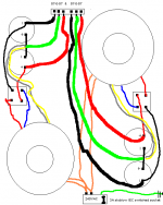
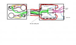
cool, so it is OK for both supplies have the same earth ?
and can this be inside the amp enclosure???
how does this diagram look?
please excuse my basic drawing skills
thanks to Rod Elliot for previous diagrams!!!
in fact - thanks to Rod Elliot for information, inspiration and down-to-earthness that has got me thus-far!!!
i will twist all the +/-57V lines together
Attachments
- Status
- This old topic is closed. If you want to reopen this topic, contact a moderator using the "Report Post" button.
- Home
- Amplifiers
- Solid State
- is my PSU layout OK?