

I think you need to wet the audience's appetite a bit.
Schematic? Anything special out of the ordinary? Tricks you did to solve a particular problem? Are these FETs special, or do they work better then others, and why?
Maybe a better quality pic?
How did you make the PCB, any tips we can use? That sort of thing.
Jan Didden
Schematic? Anything special out of the ordinary? Tricks you did to solve a particular problem? Are these FETs special, or do they work better then others, and why?
Maybe a better quality pic?
How did you make the PCB, any tips we can use? That sort of thing.
Jan Didden
Schematic and help
Ok.
I attached schematic in .pdf.
I experienced little problem with this amp.
Without load on output ( 4 ohms) everything is OK.I can adjust q-current and output voltage is almost 0.0 V.But when I connect load and start increasing power voltage to aprox. +/- 10V positive rail start to suck high current while negative is still low and I can not adjust that quiscent current any more.Negative rail MOS is cold-positive rail MOS is getting hot.I did not even try to increase voltage higher.
Please HELP.
Attachments
Hi zox2003
I have never set up this amp by turning the voltage up slowly and this is not the correct way of setting it up.
Before we get to the setting up phase though, please verify that transistor Q8 is mounted on the main heatsink and so are your output devices. Verify also that the output FETS are fully isolated from the heatsink by insulating pads. You can check this by placing one meter probe on the heatsink and the other on the middle lead of the output FETs.
Please check this first and go over your work again to verify component placement.
It looks as though you have substituted many parts in this cct. If you send me a list of what you replaced I'll verify their suitability.
Sorry we need to do this first before we turn it on again.
Good Luck

Maybe fix?
Very interesting:
I placed 1N4001 diode in paralell with emiter resistor of Q9 (220 ohms and now I do not have that problem any more.
Answer???
Also sometimes when I turn amp on output voltage goes slowly from full rail voltage to 0Volts.Problem with voltage source for input stage or what?
Very interesting:
I placed 1N4001 diode in paralell with emiter resistor of Q9 (220 ohms and now I do not have that problem any more.
Answer???
Also sometimes when I turn amp on output voltage goes slowly from full rail voltage to 0Volts.Problem with voltage source for input stage or what?
Re: Maybe fix?
The diode (depending on which way round you have it) will either have no effect or short the gate drive, turning off the output stage. This has not fixed it.
If you give me a day or so I'll re-post the cct with some key voltages on it to help you. I gotta go to bed now it's almost 2:30am here.
Cheers
zox2003 said:Very interesting:
I placed 1N4001 diode in paralell with emiter resistor of Q9 (220 ohms and now I do not have that problem any more.
Answer???
Also sometimes when I turn amp on output voltage goes slowly from full rail voltage to 0Volts.Problem with voltage source for input stage or what?
The diode (depending on which way round you have it) will either have no effect or short the gate drive, turning off the output stage. This has not fixed it.
If you give me a day or so I'll re-post the cct with some key voltages on it to help you. I gotta go to bed now it's almost 2:30am here.
Cheers
quasi said:Hi zox2003
I have never set up this amp by turning the voltage up slowly and this is not the correct way of setting it up.
Before we get to the setting up phase though, please verify that transistor Q8 is mounted on the main heatsink and so are your output devices. Verify also that the output FETS are fully isolated from the heatsink by insulating pads. You can check this by placing one meter probe on the heatsink and the other on the middle lead of the output FETs.
Please check this first and go over your work again to verify component placement.
It looks as though you have substituted many parts in this cct. If you send me a list of what you replaced I'll verify their suitability.
Sorry we need to do this first before we turn it on again.
Good Luck
Please verify the above and please tell me what voltage rails you are running.
We can then start to measure some voltages around the cct and try to locate the problem.
Good Luck
jdoorn said:After a brief look to your schematic I only wander why you have drawn
the series connection of 33R and 330pF in the first stage. It seems that it serves no function.
These reduce the amplifiers gain at high frequencies and help make the circuit more stable i.e. less prone to oscillation.
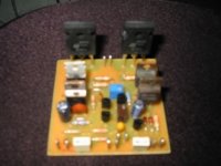
Here is my pcb of this amp.Works good, no problems with 80V rail output is 2x48V@4Ohm or 80V@16ohm brigded.With oil cooling.
http://foto.inbox.lv/albums/ezis-666/elektronika/n_ch.jpg
http://foto.inbox.lv/albums/ezis-666/elektronika/n_ch.jpg
quasi said:
These reduce the amplifiers gain at high frequencies and help make the circuit more stable i.e. less prone to oscillation.
I don't see how this should work. I see a series connection of a resistor and a capacitor, both connected to the collector of Q4.
I think the error is that the capacitor should be connected to the collector of Q5.
 I am a
- Status
- This old topic is closed. If you want to reopen this topic, contact a moderator using the "Report Post" button.
- Home
- Amplifiers
- Solid State
- NEW MOSFET AMPLIFIER USING STW60N10 Picture