I am looking to obtain a schematic and possibly some direction as to fix my NAD 2400 amp.
Here's what happened. I loaned my pre-amp and amp to a friend that was wiring his house for in-wall speakers. We had three sets of speakers (8ohm) hooked up in parallel. We were using impedance mathing volume controls (at x4 resistance setting). My friend disconnected one set of speakers (After the volume control) but did not disconnect the wiring to the volume control. He turned on the system to listen to music on the remaining sets. Music played for about two minutes and then the amp blew the main fuse (5mF 125V 7A). After consulting with an electrical engineer at work, he told me that it was a bad thing to leave the one volume control hooked up (the one without speakers attached). The volume controls were Phoenix Gold VMT100
I replaced the main fuse, plugged it in, and nearly instantly blew the fuse. I tried again and blew the second fuse. Obviously I have a problem.
Does anyone have a hypothesis as what is wrong or what is the next diagnosis step? I am thinking it is the transformer. Can someone provide me with a schematic for a 2400?
From memory, if you find the fuse is blowing straight away you will most likely find the outputs potentially are blown... Not sure on the volume control causing the problem unless it was presenting a below 4 ohm load (from memory that nad's rated to 4 ohm min? or was it 2?)... Could have caused the amp to heat up a lot and blow the outputs... Of course, make sure everythings unplugged and measure the resistance on the connections of the output transistors (relative to eachother) if any of them are REALLY low like 1ohm, something like that, they are short, blown... Potentially it's more than just the outputs too, check diodes, resistors and small transistors within that circuit, sorry but i do not have a schematic for it
Good luck
Aaron
Good luck
Aaron
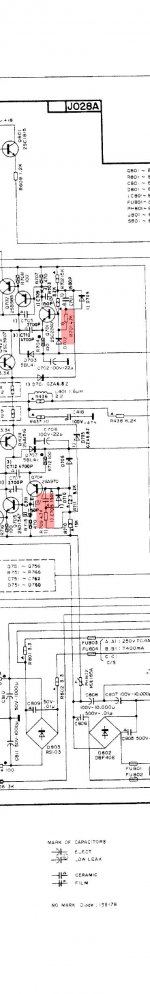
Using this thread for a question regarding NAD 2400 (thx version). R701,R709,R751 & R759 became "cold joints" due to extreme heating (started to work again when i resoldered these), as the schematic tells this is carbon resistors 1/6w rating. The problem is rating on these are very low! hotspots on pcb maybe there is a reason for it..(?).. If i replaced these with say 2w metalfilm resistors, would that be a good or bad thing??. As for carbon vs metalfilm i don´t think it will affect anyting here, but is this a design issue or made like this to fail here first?
The posted images are unreadable (if those resistors are even in that part of the circuitry) but to answer your question... it all depends on what the resistors intended function is. If its just a normal part of the circuit then no problems but if the 1/6 watt devices are a special "safety resistor" or "fusible resistor" designed to fail in the event of an overload or fault then obviously replacing with a 2 watt component defeats that.
Its a common occurrence for commercial gear to have hot spots and parts that literally fry... not saying that's what is going on here... but it is commonly seen.
Its a common occurrence for commercial gear to have hot spots and parts that literally fry... not saying that's what is going on here... but it is commonly seen.
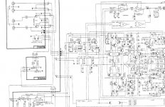
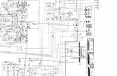
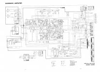
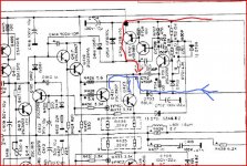
Maybe this schematic look better, seems like there is only one channel in the schematic, R751 and R759 is in the exact same position for the other channel.
When i look at this schematic now i see that fusible resistors are marked, so this is not a fusible resistor, then i would be able to use a higher rated resistor to keep things cool......
When i look at this schematic now i see that fusible resistors are marked, so this is not a fusible resistor, then i would be able to use a higher rated resistor to keep things cool......
Attachments
Last edited:
You should be OK there. That part of the circuit (rail switching Class G) can be troublesome though. Problem is, even when faulty the amp all works. I would make sure the output stage is being fed with the nominal "low" voltage supply and that transistors Q702 and 706 are not turned on. The commutation diodes are a known problem too.
Ok, i will do a full set of measuremets and adjustments as service manual says as soon as i fix these obvious resistor default/problem. When you say "low" voltage supply you refer to the supply for collector/emitter and not base (?). commutation diodes are not something i feel i know much about.... little noobish here, will have to look this up. I basicly do this to learn.... so no rush here.
The output stage (the collectors of the output transistors) runs on a "low" supply voltage. Low being a relative term in this case. The top pair for example are fed via D703 from the PSU. When the output voltage of the amp increases the "rail switching" transistors (those 3 above the outputs) turn on and switch a higher voltage on to the output stage. D703 is one of the commutation diodes that pevents this high voltage feeding back into the lower voltage rail. There is a mirror image of the circuitry for the negative rail and the same again on the other channel.
")
I found myself facing a similar problem. A NAD 2400 with one blown channel. All outputs are gone as well as 4 out of the 6 transistors in the rail switching circuit 2SB1155/2SD1706 and 2SB985/2SD1347). I will replace the outputs with 2sa1493/2sc5200 but can't seem to find any replacements for the other pairs.
I ended up replacing both the outputs and the main rail switching transistors (2sb1155/2sd1706) with pairs of 2sa1943/2SC5200, they are really close in spec. The smaller pairs of drivers for the rail switching (2sb985/2sd1347) were replaced with 2sb1203/2sd1803. They're all available at mouser. It's a little tight fitting all these transistors as they are bigger but the mounting wholes line up fine and the amp works perfectly.
Last edited:
- Home
- Amplifiers
- Solid State
- NAD 2400 problem - need help