Nelson/ others,
I read about your comments about the effect of reducing feedback, and I tried it in my Adcom 555. I loved the bass after the reduction, I increased the FB resistor (R123) from 22k to 30k.
Issue is now I hear a little more noise and hum at the speakers (ears about 6 inches from the speakers). While not a biggie, I'd like to take care of it.
Is there some standard calculation for feedback resistors and input impedance resistors (R102 and R103) whereby gain can be kept same as it was before reduction of NFB resister?
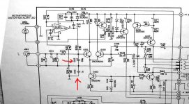
Schematic attached for reference: please disregard the red highlights.
thanks in advance!
I read about your comments about the effect of reducing feedback, and I tried it in my Adcom 555. I loved the bass after the reduction, I increased the FB resistor (R123) from 22k to 30k.
Issue is now I hear a little more noise and hum at the speakers (ears about 6 inches from the speakers). While not a biggie, I'd like to take care of it.
Is there some standard calculation for feedback resistors and input impedance resistors (R102 and R103) whereby gain can be kept same as it was before reduction of NFB resister?
Schematic attached for reference: please disregard the red highlights.
thanks in advance!
Attachments
I'm impressed with the adcom designer's trust in component tolerance;
the current balance in the diff pair is strongly influenced by Vbe and Vf differences of 3 different types of transistors and the bias diodes - even assuming the diff pair Qs match perfectly - toss in some R tol and possibly line V effects too
for repeatable performance and low distortion the diff pair Qs must match and be biased within < 1 % current balance - without degeneration or trimming I don't see how this can be expected in production
I would go for current mirrors for bias balance alone, but I would also welcome the extra loop gain
if you want to "spend" some of the loop gain, degenerating the diff pair might be the best place to swap some global gain for linearizing local feedback - degeneration won't fix current imbalance but it gives you a good place to measure it and then you can trim the bias elsewhere (trim collector load R or VAS bias R)
jcx said:I'm impressed with the adcom designer's trust in component tolerance;
R)
That be da Pass man!

JCX,
If I understood you, your solution would be to add a couple of resistors on the Tails (emitters or collectors) of Q101 and Q102 to reduce (and linearize) the gain as opposed to modifying the value of R124 to something like 1.35k?
If so, approximately what values do you suggest?
I am leery of playing with the input diff pair because of modifying the distorition spectrum, absolute value or even sonic qualities (or lack of) in the amp. Basically it wil cease to be a 555. (For bette or worse).
K-
I'm not an advocate of reduced loop gain, but if that’s what you want to explore;
assuming d103,4 are Si diodes, tail current ~= 2 mA, 1 mA in each input diff pair Q gives 1/26 mho gm, adding 26 ohms in series with each of Q101,2 emitters reduces loop gain by 2x, 52 ohms by 3x, 78 ohm 4x, ... http://www.dself.dsl.pipex.com/ampins/dipa/dipa.htm discusses input pair distortion about 20% down the page
adding the assumption that the VAS output sees a large resistance, ie not a shunt R, then you could try 50 and 100 ohm degeneration R in the input ~= 3x and 5x loop gain reductions
carefully matching the emitter degeneration Rs to << 1% lets you measure the current balance by measuring the deltaV at the diff input emitters
adjusting R105 collector load or one of (R112+113) or R116 lets you exactly balance diff Q currents - assuming they are well matched in Vbe, Hfe
there is a small noise penalty for emitter degeneration but as long as emitter R < ~1/3 of the feedback network R or input series R it shouldn’t be noticeable
hobbyist equipment may not be adequate to make sub mV measurements - if you have the resolution, averaging measurements with alternating lead polarity could remove some fixed offset
digital multimeters may require a cap across their input and a series R to prevent digital sampling noise injection into the input Qs Vbe junctions causing offset from rectification - or at least series R >>10X the emitter R to keep meter input C from affecting amp stability
Hope I'm not too late for this discussion...
K-Amps, yeah, I read the feedback post too and had to double-think my education when the author of the post said 30-33k ohms.
FWIW - I worked at the "factory" for Adcom Service, Technical Support & finally Product Development many years ago, and I currently modify/optimize Adcoms for fun & profit. Up until now my big secret was to match the input pairs.
I do this with with a voltmeter with hfe measurement capability - this will essentially give you the gain of the DUT. What you need are a handfull of transistors (2SC2362 for 555II or 2SC2240GR for 555) and some time. Go through and measure all of the transistors and write the values down - once complete, select the four highest values with the closest matching numbers, i.e.; 677 & 676 for one channel and 650 & 650 for the other channel. Ideally, you should measure these values at operating temp, but room temp is ok as long as you don't hold the transistor (and warm it up).
I really dig this forum - on the one hand, I'm overwhelmed by the technical competence here, on the other hand, there does seem to be a bit of misinformation as well. I just read that Adcom matched their output devices on the 5xx series - that's new to me! They never matched BJT devices, and they barely match the MOSFETS on the newer amps. FWIW - when I was in the service department, most of my co-workers replaced parts and nothing more - they did their job, met their quotas, and got a paycheck - I was one of the few poeple who worked there who actually cared about audio and could hear a diffefence....sheeh.
Most Adcom 2ch amps are brilliant designs, but Adcom kept/keeps the price low by losing focus on the little details that add up to make a truly fantastic piece of gear.
Oh and about feedback - if you want to change the "hue" of the Adcom "color" then try different types of resistors in the feedback path - the effect is rather dramatic.
Good luck,
-JamesW-
James,
Excellent post and very helpful thanks!
Yes I have tried different values for R123 and the effect is rather dramatic. Very nice indeed.
I will take your advice on matching the input diffs, seems like a very good idea knowing that they were not matched. I have had very good successes with weaking the 555's, excellent amp for the money. My fav Adcom is the 545ii, so natural. A power supply upgrade on that and man it sounds nice.
The 5802 is just like my old Hafler Dh500, nice mids, nice bass but terrible highs. Actually they are so smeared that I cannot even call it hi-fi. I'd hate to call it a MOSFET characteristic but for now thats all I have....
K-
Do you have a way to identify the actual center frequency of the buzz/humm? That could give some of the readers more ideas on possible solutions.
When you wrote 33k being substituted for 20k my first thought was "Johnson noise, maybe?", but that would be more of a hiss, I think, than a buzz.
If the the noise is centered around 100-120Hz, it is likeley related to the power rails some how. Since it arose after modifying the NFB it seems possible that is entering via the arm of the NFB net that connects to ground. Self comments on this and suggests increasing the cap on the lower arm of the NFB network, but I'm not sure how amenable the Addcom is to this.
Maybe someone with a better understanding of the Adcom would care expand on this.
Sam,
Just plain old 60Hz hum. I think by reducing the FB factor and the resultant increase in gain, there is a slight increase of the noise floor and hum artifacts.
It could be considered normal for some amps, like for example after modification, the hum is still less than a stock Adcom GFA-5802 (which is a MOSFET design and has very low feedback IIRC via a 100k resister.)
How ever you "Johnson Noise" thoery is interesting... I guess I will have lug out Self's book from the basement,
K-
sam9 said:Self comments on this and suggests increasing the cap on the lower arm of the NFB network, but I'm not sure how amenable the Addcom is to this.
Maybe someone with a better understanding of the Adcom would care expand on this.
That may be a possibility - I haven't played around with a mkII in a while, but it looks like the input floats 100 ohms above ground. I believe the noise was just from the increased gain and susceptibility to noise at the input - Adcoms can be niosy sometimes and I've learned time & time again that careful wire routing substantially reduces noise in these amps.
I am not a big fan of the DC servo in this amp as I feel it has the potential to add noise, makes the amp more complex, and subtracts from the musicality of the original 555. There is no denying though, that the mkII has way better bass, mids & highs than the 555, but it (IMO) loses some "character" in the process.
Can't say for sure about the Adcom, but I am not very amenable to Self as I have subjectivist proclivities
woodman said:
Can't say for sure about the Adcom, but I am not very amenable to Self as I have subjectivist proclivities
Me too hence my desire to play with it. The thing I do not like about the older 555 is it's blaring quality in the 2kHz to 3khZ region.
Yes the 555ii is a little noisy and the noice is noticeable from 4 feet in case you have the amp bridged.
However it is a tweaker and DIY'er dream amp, so much potential!
K-amps,
Johnson noise is the noise floor of any resistor. The higher the value of the resistor the higher the noise. I'm not up on the theory, but I think I've read it is random thermal noise. It is very low and could be ignored exceprt when it ocurs in in a circuit which will be subsequently amplified. Input sections of an amp are an example and it becomes for of an issue the higer the gain.
Anyway it doesn't sound like what you have. Since it's origin ripple in the rails or leaking into the grounding network tghose are the places to look. Even if you don't care for Self otherwise, his books and articles are quite useful if you are trying to nail down the source something as unambiguous as AC hum. I don't think I've heard and debates about the subjective value of hum- just about everyone thinks it sucks and would prefere to do without. Although my last few amps have not been Self-clones by any means, I have used his grounding schemes and never hat a hint of humm. Maybe something as simple as improved bypassing is all that you need to get rid of it. In fact is this unit old enough that the bypass electros may be starting to deteriorate.
- Status
- This old topic is closed. If you want to reopen this topic, contact a moderator using the "Report Post" button.
- Home
- Amplifiers
- Solid State
- Reduce NFB but keep noise/hum down?