Banned
Joined 2002
Well Dave ( planet10 ) and i have asked Brian-Gt to d up a nice board layout for a 15V regulator for op-amp's and other things that i am currently Building. Is any one interested in some of these board for there home op-amp's and active X-over's ? Schematic and board layout will be posted...
Attachments
Banned
Joined 2002
jleaman said:I dont see any point in that. The pourpose of this board is to have every thing on a small board INCLIDING the small board mountable Tranny.
Maybe for you... but for someone with a whole bunch of transformers that won't fit there, and who would prefer to use a trafo that isn't subject to DC-offset, it is just a waste of board space.
dave
Banned
Joined 2002
I would suggest doing the board with a transformer, with the option of separating transformer's section off, if someone doesn't want it (with one scoring line). The difference in price for an extra transformer space should be negligable, and such board would accomodate everybody.
Also, footprints for TO220 diodes would be nice to have.
Also, footprints for TO220 diodes would be nice to have.
Banned
Joined 2002
Peter Daniel said:I would suggest doing the board with a transformer, with the option of separating transformer's section off, if someone doesn't want it (with one scoring line). The difference in price for an extra transformer space should be negligable, and such board would accomodate everybody.
Excellent idea Peter... you are getting quite adpet at making one design jump thru many hoops... i have an XO design in my head that will try to do some of that too...
dave
jleaman said:How big of a transformer do you Plan on useing ? And.. These are not toroidial transformers were useing here either. :
Salvaged EIs most likely (bigger, need to take care with shielding, but don't suffer from DC saturation -- and most importantly are already on hand).
The trafo spot looks the same as the one Brian designed in for his prototype phono baord which was a potted toroid.
dave
planet10 said:... it would be nice to have one without space for a transformer.
Seconded.
")
Banned
Joined 2002
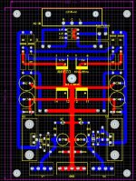
I made this layout a while back, and it was just a quick job. I will look into revising this layout after I finish the miniALEPH stuff.
I was planning on using MUR860 diodes, as I have been using with all of my other projects, but for some reason I started the layout with the MUR460 diodes in mind (large axial lower current versions of the MUR860)
As for the scoring idea for the transformer, I will look into this.
The original idea for this board was that it was designed to fit inside the LMB Heeger extruded aluminum chassis:
http://www.lmbheeger.com/products.asp?catid=68
(300 or 400 model [4" x 6"])
I made the form factor for the chassis, but never fully optimized the design.
It will be a little while until I have time to finish the pcb layout for this project, as I want to get a few other things done first.
--
Brian
Banned
Joined 2002
Banned
Joined 2002
jleaman said:No it has to be done tonight you are not alowed to go to sleep till this is done LOL..
Send me the schematic and ill make a board layout then. : O )
Tonights projects were:
Assembly of the new 3875 rev.3 power supply board:
http://www.diyaudio.com/forums/showthread.php?postid=592781#post592781
and
Initial assembly of the Mic preamp boards:
http://www.diyaudio.com/forums/showthread.php?postid=592886#post592886
I will find time to finish up the layout soon. Lets see if we can get some more constructive feedback on this project.
--
Brian
Also, regarding this regulator power supply, it is based on the LM317 and LM337. The output voltages are not limited to only +/- 15v. The voltage is adjustable by changing the resistors (see datasheet for formula). And the current is limited by the 1.5 amp rating on the LM317 and LM337. The output voltage range (from the datasheet) will be +/- 1.2v (ref voltage) to +/- 37v. The transformer should provide a rectified DC voltage less than 15v greater than the desired output voltage, and must be at least 3v greater than the desired output voltage.
--
Brian
--
Brian
- Status
- This old topic is closed. If you want to reopen this topic, contact a moderator using the "Report Post" button.
- Home
- Amplifiers
- Solid State
- 15V + - Regulator Board Brian GT Board.