Chatty bunch around here, aren't they?")
And I still think the answer is 'yes', but:
1. Turn it into a personal project...in other words, do it yourself.
2. Don't expect sonic bliss from an ST120...it was a stepping-stone on the road to high-quality SS amps, and has a strong place in history, but though a restored ST120 can sound pretty decent, just don't listen to a really good amp for a few hours after, else you are likely to discover the same thing that a lot of other ST120 owners did once really good SS designs began to appear and they relegated the Dynaco to a corner of the closet.
OK, I will go out on a limb with nothing but my memory to back me up. Back in the early 70's I breifly owned a ST-120 with a Dynaco outboard capacitor upgrade, which alleged more power.
Several friends owned ST-70's at the same time..... the ST-120 wasn't even close. The ST-120 quickly made way for a SWTP, Stereo Tiger, which for some odd reason I liked more.
Cyclotronguy
Several friends owned ST-70's at the same time..... the ST-120 wasn't even close. The ST-120 quickly made way for a SWTP, Stereo Tiger, which for some odd reason I liked more.
Cyclotronguy
I recently pick up a dead Dynaco 120,after I fix it,I found the amp had some
crossover distortion,and those 300 Ohm resistors had cause PCB burned. I had
modify the circuit with good result,distortion lower, put out more power
before clip than original circuit.
I know this is old thread,but may be some one interesting to try it out too.
crossover distortion,and those 300 Ohm resistors had cause PCB burned. I had
modify the circuit with good result,distortion lower, put out more power
before clip than original circuit.
I know this is old thread,but may be some one interesting to try it out too.
Attachments
I recently pick up a dead Dynaco 120,after I fix it,I found the amp had some
crossover distortion,and those 300 Ohm resistors had cause PCB burned. I had
modify the circuit with good result,distortion lower, put out more power
before clip than original circuit.
I know this is old thread,but may be some one interesting to try it out too.
crossover distortion,and those 300 Ohm resistors had cause PCB burned. I had
modify the circuit with good result,distortion lower, put out more power
before clip than original circuit.
I know this is old thread,but may be some one interesting to try it out too.
Getting rid of the crossover distortion at very low volume is the goal of djoffe in this thread:http://www.diyaudio.com/forums/solid-state/156627-dynaco-stereo-120-can-beautiful.html
It appears you have tried to do the same with a much lower parts count. I presume the 30-40 ma you are talking about is the current across the .47 ohm resistor between the top and bottom output transistor.
Your circuit appears to have the disadvantage that if the pot wiper loses contact, something awful happens. I like the parts count, but not that effect.
My ST120 I always played loudly enough (1v PP average out), I never noticed the crossover distortion. But if you turn the input down enough, it is there.
The tremendous advantage of these is that if something goes wrong, the series cap protects the speaker very cheaply. The disadvantage of these is that the 1/8" aluminum flanges used as heat sinks heat up if you use more than 1 v pp for more than an hour or two.
Have fun. I've built and installed the djoffe transistor bias circuit. I'm not using mine now because there is a thermally sensitive joint in there on PC14, that the djoffe circuit I built physically covers up. I'm waiting until the rains of winter to dig into it again, when I will build new mount brackets just for debug. When both channels are working, it sounds very good at 1v PP, very similar to the peavey CS800s I bought last year. Both st120 with joffe bias and the cs800s sound better than the tube dynakit ST70 I am actually using, but as is usual, tubes are so **** easy to fix that I am using the ST70 this summer without thinking about it.
I did put PCAT fans on the heatsinks of the ST120 like micky mouse ears, so I can leave it on all day and not worry about it melting the solder off the output cap. When that melted and the lead sprang up, it cause a ball of fire under the lectern at church 10 years ago at the end of a 3 hour Christmas Cantata rehearsal. The junior choir was very entertained. The ST70 came to the rescue that time, too, worn out 6CA7's and all. Hint- if you use snap in output caps (3300) , glue them through a lexan board and loop the wires to it through the board for strain relief before soldering them to the snap in cap.
Last edited:
Shameless commerce division...
with apologies to frick and frack, the tappet brothers, of cartalk fame...
I make a chipamp kit to replace the amplifier modules of the Stereo 120...
check it out at:
Update My Dynaco
with apologies to frick and frack, the tappet brothers, of cartalk fame...
I make a chipamp kit to replace the amplifier modules of the Stereo 120...
check it out at:
Update My Dynaco
Djoffe, I want to keep the original pcb with minimum components change.
Indaianajo, I had changed again, the update version I removed the diodes and
pot,I only used a red LED for the bias,the bias voltage on the LED
is around 1.835 volt one channel and 1.850 volt on other channel.
I also parallel the 35 uf cap to LED which I removed from the pcb
early.
I found out high idle current sounds better to me,with the red LED
as bias,the idle current are 250ma on one channel and 300ma on
the other, I had to add more heat sink for high idle current to avoid
over heat.
I may match the LEDs later.
Attachments
High Idle current
I have no doubt that the high idle current would sound better, as I'm sure it dramatically reduces the inherent crossover distortion. I'd be a bit worried about thermal runaway, though...but I guess the right combination of larger heatsinks and appropriate tempcos in the bias LED, plus the right thermal coupling, might be able to stave off those problems.
I have no doubt that the high idle current would sound better, as I'm sure it dramatically reduces the inherent crossover distortion. I'd be a bit worried about thermal runaway, though...but I guess the right combination of larger heatsinks and appropriate tempcos in the bias LED, plus the right thermal coupling, might be able to stave off those problems.
250 ma idle current seems a bit excessive since the djoffe closed feedback bias circuit mod sounds fine at 20 ma idle current. If I leave mine on all day it heats up significantly with fans on the output flanges, and I have TO220 heat sinks on top of the output transistors. I found some of those low flange heat sinks from thermalloy, so they are waiting to go in next time I work on it.
I looked at the schematic pwgtang, I am vague where the 35 cap goes. Right across the led? It is not on the schematic.
Would 1.2 V (2 silicon diodes) instead of a LED achieve 2/3 the O.T. idle current? This is beginning to look like dynaco's original circuit, minus the zener. The dynaco circuit, as I understand, had to charge up the non-polar capacitor before it would produce output idle bias current, and soft music played softly would not do the job.
I like playing with the original parts, I can still get O.T's made in the western hemisphere and don't need to import a lot of expensive parts. The way I'm scrapping out PC power supplies and free haul it away organs, my supply of salvage signal transistors is also unrestricted.
Last edited:
I changed the ciruit to direct coupling,don't need the 35uf NP cap. as coupler.
so I parreller it to the LED.
The idle current I measured are after the amp power up half hour.
The heat sink is hot,but still ok to touch.
I keep most of the original compoments except add a red LED.
The sound is really good after this modify.
so I parreller it to the LED.
The idle current I measured are after the amp power up half hour.
The heat sink is hot,but still ok to touch.
I keep most of the original compoments except add a red LED.
The sound is really good after this modify.
Revised Update My Dynaco Website
You can now buy super heat sinks to make an even stronger retrofit of the Dynaco Stereo 120 with LM3886 based chip amps. Each channel will deliver more than 100 Watts into 4 Ohms. Details here:
Update My Dynaco
You can now buy super heat sinks to make an even stronger retrofit of the Dynaco Stereo 120 with LM3886 based chip amps. Each channel will deliver more than 100 Watts into 4 Ohms. Details here:
Update My Dynaco
I always had ~80v voltage rail. Still do. When I first repaired it in 1985, I had no manual or schematic and the regulator board was so burned up I couldn't tell if the TO3 transistor was NPN or PNP, and it was my first SS amp, so I didn't see 80V rail as unusual. I just make sure all the parts I buy are rated 100v or better: easy after 1985 when I bought it, not so easy in 1966 when it was designed. I went right to NTE60 output transistors, and then NTE181MP, as that was what the store in town carried. (no internet)
60 w/ch power rating was 8 ohm load, weren't too many 4 ohm speakers in 1966. Started seeing them on car radios about 70, as permanent magnet technology got better and cheaper.
Modern transistors are a lot faster (ft) and higher gain at high currents than they were in 1966. What O.T's are you using? Mine came with RCA TO3 transistors 4xxxx, not crossable to anything. I had to use one of those for the regulator circuit, the NTE60s had so much gain it was limiting the DC rail current out to 2 amps, when the limit should be 6.75 amps. I'm using NTE49 & 50 for drivers, TO220 100V parts.
Last edited:
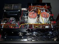
Stereo 120 teardown and rebuild (partial)
Here's the youtube link:
Dynaco Stereo 120 Extreme Tear Down and Cleanup - YouTube
Here's the youtube link:
Dynaco Stereo 120 Extreme Tear Down and Cleanup - YouTube
Considering that just about everybody on this forum has 1000X
more comprehension of electronics 101 than I do, I offer this
as my purely experience-based $0.02:
DON'T drive that thing hard into a 4 ohm load in its stock configuration.
Without serious upgrades, I wouldn't let one of those touch sub
8-ohm-nominal with a 10 foot pole. Maybe the ones I've had were
all lemons or something, but I've seen the blue flash and smelled the smoke.
Dynakit ST120 had heat retention problems by design. I put 2 fans on mine, solved the problem. I'm running it 15 hours per day every day, for months, no problem at 1 Vpp output. No matter how big the flash (my last fireball was about one foot in diameter when the solder melted off the output capacitor hookup) they don't damage speakers due to the output capacitor. If you tried to run 60 W continuously, as I was close to at church for 3.5 hours at the last meltdown, it may need modern finned heatsinks.
Last edited:
Yeah, fans, heatsinks... hmmm, maybe someone can invent a liquid-cooled
upgrade like gamers use on their PC towers
The two I had were factory, not kit, and in both cases melted down after about
3 minutes of serious drive into 4 ohm nominal. But you're right, at least they don't
take out speakers like the Flame Linear can. Sounds like your light-show
was better than mine, though. I'm kinda jealous.
Mainly I just wanted to spare people the grief potential of running hard un-modded
into 4 ohm nominal. Just say no, kids.
- Status
- This old topic is closed. If you want to reopen this topic, contact a moderator using the "Report Post" button.
- Home
- Amplifiers
- Solid State
- Dynaco ST-120