Hello everybody!
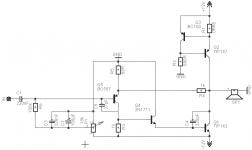
I found this diagram in the last issue of "Nouvelle Electronique". It is a simple class a amplifier, 10 watt output power, 10Hz to 100KHz. All resistors are 1/4watt. Nothing to tweak.
I am not sure on the wrightness of the diagram: R5=R6=18K???.
C2=220uF but C1 1000uF????. can anybody tell me, is this correct???.
Can I use a double power supply +- 12V by conecting C3 at 0 volt???.
And in general it is a useable/good diagram?
Thanks !
Attachments

arex said:
I am not sure on the wrightness of the diagram: R5=R6=18K???.
Yes...correct! Is for the middle point at the output , to be at half the supply voltage.
C2=220uF but C1 1000uF????. can anybody tell me, is this correct???.
C2 must be at least 2.200 uF for good low frequency response , with a 8 Ohm load.
I made a mistake: T1 is a pnp transistor.
T1 in your second schematic must be connected with emitter to C3 and T3 must be a PNP transistor.
arex said:I made a mistake: T1 is a pnp transistor.
The correct schematics joined:
No, no, no
T1 was OK, T3 wasn't
cheers
edit: Jorge was first, ignore
WRONG again! T3 is a pnp too.
Excusez moi svp. THIS IS THE WRIGHT DRAWING.
Can I use a dual power supply by conecting C3 on 0 volt and eliminating C2??
Comparing with the JLH amp: the resistor on the Q2 colector (JLH) in a 7watt one.
Here (nouvelle electronique) the same resistor in the T4 emiter is a 1W ( 0.25 x 4). Why?
Thanks
Attachments

arex said:
Can I use a dual power supply by conecting C3 on 0 volt and eliminating C2??
No , because that way , the offset will not be controlled...
Here (nouvelle electronique) the same resistor in the T4 emiter is a 1W ( 0.25 x 4). Why
Because in your schematic the dissipation in that resistor is ~ 0,6W..so 1W is enough .
Attention in your last schematic T1 is still up side down

Yes;
Thank you. This is what I wanted, but I don't realise by myself if your schematic is right. Comparing with JLH 1996 (see bellow), it seems to be a simplified version. Why did you changed the T1 base polarisation (R5=R6 in the initial drawing)?
Somebody else comments?
Thank you. This is what I wanted, but I don't realise by myself if your schematic is right. Comparing with JLH 1996 (see bellow), it seems to be a simplified version. Why did you changed the T1 base polarisation (R5=R6 in the initial drawing)?
Somebody else comments?
Attachments
eLarson:
Tip142 is a darlington transistor which has internal on-chip resitors ie 8k, but if we add smaller value we speed-up amp...
I think that standard Miller compensation is good enough (C4), 47p is initial value...
regards,wk.
for me current is too small...
R1=0.47R then I=0.7/0.47 =1.5A
1.5 x 24V = 36W per channel
Tip142 is a darlington transistor which has internal on-chip resitors ie 8k, but if we add smaller value we speed-up amp...
I think that standard Miller compensation is good enough (C4), 47p is initial value...
An externally hosted image should be here but it was not working when we last tested it.
regards,wk.
for me current is too small...
R1=0.47R then I=0.7/0.47 =1.5A
1.5 x 24V = 36W per channel
- Status
- This old topic is closed. If you want to reopen this topic, contact a moderator using the "Report Post" button.
- Home
- Amplifiers
- Solid State
- nouvelle electronique