Can this transistor be used in Amplifiers and any idea how?
Schematic?
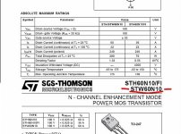
I have about 20 pcs.Check data sheet attached.
http://www.st.com/stonline/books/pdf/docs/3105.pdf
Thanks
Schematic?
I have about 20 pcs.Check data sheet attached.
http://www.st.com/stonline/books/pdf/docs/3105.pdf
Thanks
Schematic needed
I doubt you would find complimentary FETS to match so you will probably need to use a quasi-complimentary class A/B amplifier cct.
Feel free to check out my cct under the thread "Power Amp Under Development".
One pair (one FET per rail) of the 200 watt version would give you at least 100 watts of music into 4 ohms using rails of around 45 volts. Caution though, prolonged sine wave at full power will probably destroy it.
As richie00boy suggested I would not go above 50v, I personally would not go above 47v. This means that you can use 50v capacitors in your power supply and these are fairly cheap when compared to 80v+ ones.
Cheers
Did you not read quasi's post, particularly the second paragraph?
You have to be prepared to help yourself a little, why should we spend our time spoonfeeding people. If it looks like you have made some effort researching then we will be more than happy to help out")
Lars Clausen has also posted an n-channel design, but there seems to be some loose ends on that one. A search for "Zeta" will get you all the info you need on that one.
You might also like to search for "MOSFET Citation 12" as somebody posted a design based on this with boards and everything. Looked really nice.
You have to be prepared to help yourself a little, why should we spend our time spoonfeeding people. If it looks like you have made some effort researching then we will be more than happy to help out
Lars Clausen has also posted an n-channel design, but there seems to be some loose ends on that one. A search for "Zeta" will get you all the info you need on that one.
You might also like to search for "MOSFET Citation 12" as somebody posted a design based on this with boards and everything. Looked really nice.
possible problem or what?
OK,
i see a lot of schematics here for mosfet's but I want to know if this FET is usable in this schematic's and which one?
Also,
Long time ago I built MOS amplifier but it did not work well.I basically removed bipolar transistors from output and replaced with this mosfet's.(2X BC546 input,TIP31 and 32 drivers,+/- 45V,
2X Mosfets-one per rail)
I experienced strange problem:
-When I feed amp with input signal everything worked until one point and then one of the rail mosfets start sucking a lot current and gets overheated.I turned amp off,restarted and everything was fine.I repeated same action and same thing happend.
Does anybody could explain what is problem?
REgards
You can change many amps that use transistors in the output stage to use mosfets. But, and it is a big but, you need to make some changes.
1. You need to change resistors in the Vbe multiplier (T8 in my cct) to correctly turn on and track the output FETS. When the FETs get warm the Vbe multiplier must sense this and reduce the bias drive. This is probably not happening with your modifications i.e. the current increases when the FETS get warm and you are experiencing good old "thermal runaway".
2. You need to change the driver stage from a current drive to a voltage drive. The simplest way to do this is to drive into a resistor that connects to the gate & source lead of the FET. This is how you apply the gate to source voltage to turn the FET on. If you do not do this you will not be able to control the FET correctly. On my cct these are the two 220 ohm resistors on T9 and T10.
3. Because FETS are generally faster you may need other circuit modifications to prevent oscillations.
Your FETS can be used instead of the IRFP450's but remember you must limit your rails to under 50v (45 for safety). You can also change T1 and T5 to BC546's as the 2SC1845's are hard to find and expensive. You could change R3 and R16 to 22k to better match your voltage rails beacuse you will not need as much gain. The rest of the cct is fine for your needs. Transistors T6, T7, T9 & T10 must be mounted on a small heatsink as they will dissipate around 3 watts of heat. This can be the same big heatsink as your output FETS. Transistor T8 must be mountd on the same heatsink as the output FETS and as close as possible to them.
Good Luck
Attachments
In addition to the points that quasi has raised, I would also add (and I suspect that this could also be your problem) that with MOSFETs you need to use gate stopper resistors of between 100 and 560 ohms (this must be determined empirically) as close to the MOSFET gate terminal as possible. This is because of the gates susceptibility to track inductance; the resistor swamps it out.
Also note that there are two kinds of MOSFETs, lateral and vertical. The IRF and their counterparts mainly for switching are vertical and can be a reasonable replacement for transistors, their pinout (assuming TO220 or TO247 case) is the same. Lateral MOSFETs are often sold as 'audio' MOSFETs because they have more linear Vgs/Ids curve. Their pinout is not compatible with transistors of the same plastic case type.
Also note that there are two kinds of MOSFETs, lateral and vertical. The IRF and their counterparts mainly for switching are vertical and can be a reasonable replacement for transistors, their pinout (assuming TO220 or TO247 case) is the same. Lateral MOSFETs are often sold as 'audio' MOSFETs because they have more linear Vgs/Ids curve. Their pinout is not compatible with transistors of the same plastic case type.
How much Power?
The maximum power you will get from this or similar ccts with a mosfet output stage with 45v rails will be approximately;
8 ohms = 90w RMS
4 ohms = 170w RMS
2 ohms = 310w RMS
This assumes a power supply with around 5% regulation to full power capability i.e. a big one 800va transformer 50,000uf capacitors etc.
Music power will be approximately;
8 ohms = 110watts
4 ohms = 190 watts
2 ohms = 340 watts
Music power figures disregard the regulation factor of your power supply because this is less relevant with music "pulses"
Ulimatly the actual power you get will depend on many things inlcuding the actual mains voltage at the power point on any given day.
To get 200 watts RMS into 4 ohms with this cct you will need a strong power supply with 49 volts per rail. Too close for comfort for me and you will not hear the difference between that and 170w.
But hey if you use 3 of your FETS per rail then you should be able to run music power into 2 ohms = awesome.
Cheers
- Status
- This old topic is closed. If you want to reopen this topic, contact a moderator using the "Report Post" button.
- Home
- Amplifiers
- Solid State
- Stw60n10-amplifier ???