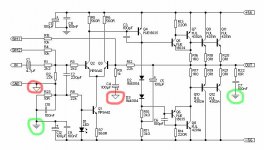
They represent ground and/or earth. There are several symbols used for that and the exact usage varies, but in this case it looks like the plain triangular ones show signal ground and the stripey ones (which commonly denote physical earth, but not in this case) are power ground (which will be connected to signal ground at the PSU, but should be kept separate on the amp PCB.
EDIT: If you're new to this, you might not want to start with something that has such high supply voltages. +/-56V is potentially dangerous!
EDIT: If you're new to this, you might not want to start with something that has such high supply voltages. +/-56V is potentially dangerous!
This obviously a modification (additional ourput devices) of Rod Elliott's P3A. The "SIM" connections are unique to the P3A. From the nature of the post, I suspect the poster is innocen intent , but Rod has an IP interest in this design and posting it without permission may expose the forum to a legal liability. On top of this, if somone is circulating this as their own work, there may be an issue as well.
Hopefully, one of the moderators will look into this.
Hopefully, one of the moderators will look into this.
sam9 said:This obviously a modification (additional ourput devices) of Rod Elliott's P3A. The "SIM" connections are unique to the P3A. From the nature of the post, I suspect the poster is innocen intent , but Rod has an IP interest in this design and posting it without permission may expose the forum to a legal liability. On top of this, if somone is circulating this as their own work, there may be an issue as well.
Hopefully, one of the moderators will look into this.
exactly why i was asking
")
its almost verbatim aside from the cap on the top-left and some diodes and probably a few other things
oh, i didnt even realize that it was the p68 schematic (never looked too deeply into that one)
i bet the esp logo just got cut out when he edited it to circle the ground symbols. its probably not a rip. i thought it was a rip with added things on perhaps someone elses site. now that i see p68 im prety sure thats where he got it from, rod's site, and perhaps doesnt know how to save/edit files and cut a bit off? who knows. but it probably isnt a rip. i thought it was someone else that slightly modified the p3a so thats what made me suspicious.
i bet the esp logo just got cut out when he edited it to circle the ground symbols. its probably not a rip. i thought it was a rip with added things on perhaps someone elses site. now that i see p68 im prety sure thats where he got it from, rod's site, and perhaps doesnt know how to save/edit files and cut a bit off? who knows. but it probably isnt a rip. i thought it was someone else that slightly modified the p3a so thats what made me suspicious.
Ahmad_tbp,
There was nothing wrong about your question or attempting to build the amplifier. The only problem was posting the image of the schematic without permission. It may look simple, but until you have yourself created a design of your own and labored on it month after month until it works the way you want, you cannot apprreciate the value that such an image holds. It's not only your own time that is expended, but as you build one prototype version after the other the financial cost of all PCBs and components adds up.
If you had stated the question and then refered to the project number on the ESP site rather than posting it wverything would have been fine.
thnx a lot all for help ! ...
i know u r right , it s Rod Eliot p68 ...i just cut his name on top of the schematic , cuz i didnt want the moderator to prevent displayin that image until gettin permission ...
& thank u all so much ! , i just ask u some question , and when i m cameback that s what i see ... 10 replays just talking bout copyright ! ... do u know what i learned since i joined this site ? .. i shoundnt count on anybody help ... thank u so much ... i m tryin not to ask u anymore question .. farewell .
Ahmad_tbp said:[snip] i just ask u some question , and when i m cameback that s what i see ... 10 replays just talking bout copyright ! ... do u know what i learned since i joined this site ? .. i shoundnt count on anybody help ... thank u so much ... i m tryin not to ask u anymore question .. farewell .
You got a quick answer to your question, PLUS some free advice that will help you stay out of trouble. You got a great deal, IMHO, and all for free. You know that, don't you?
Jan Didden
People here often forget why they are here. That's why you get so much lawyers and someones PR's in here. If anyone has a problem with the starting post - go to court with it or let Mr. Rod to do so. Or, you could help the guy out.
Those grounds in red are small signal grounds. They should be tied together and connected to the star ground in the PSU. The ones in green are "large" signal grounds and should be also tied together and with a separate lead tied to the star ground in the PSU as well.
Huh! Am I a pirat now?
Regards to ya all.
Quattor said:Those grounds in red are small signal grounds. They should be tied together and connected to the star ground in the PSU. The ones in green are "large" signal grounds and should be also tied together and with a separate lead tied to the star ground in the PSU as well.
thnx man , u said i should tie small signal qround together & larg signal ground together & connect them to star ground in PSU with a separate lead ..
Ahmad_tbp said:...i just cut his name on top of the schematic , cuz i didnt want the moderator to prevent displayin that image until gettin permission ...

That would usually be a sinbin offense, don't do it again...
BTW, that is not really an amp to attempt for a first project.
On your PCB all small signal grounds are tied together (copper leads). All large signal grounds are also tied together via copper leads. Between them there is no connection. They should not be connected together on this place. Take one wire and connect small signal ground from your PCB to the ground on the PSU. Take the other wire and connect large signal ground on the same point on the power supply. And that's it. If you need more help on this, try searching this forum on this subject. You'll find schematics, block diagrams and much more valuable information on this subject. BTW, your amp. will work even if you tie all the grounds together on the PCB and connect them via only one wire to the PCB, but you wont get the best of the amp that way.
Here is some really good help:
Goto www.sound.westhost.com
Buy Rod's original PCB, then follow the instructions that come WITH that PCB and build your amp
Other then that, I think you might want to find a smaller project to get you started
\Jens
Goto www.sound.westhost.com
Buy Rod's original PCB, then follow the instructions that come WITH that PCB and build your amp
Other then that, I think you might want to find a smaller project to get you started
\Jens
Ahmad_tbp said:...My heart is aching nevermore
for I know that all may end...
You should try Shakespeare, Ahmad.
If you intend to build this amplifier you need to know a lot more.
The amplifier needs a powersupply, doing that one wrong can be dangerous.
You will need some basic knowledge on how to put the components on a board at least.
Things as star ground, earth and signal ground, knowing how to place components, and which components to use, are basic knowledge you need before even considering to build something.
If you try this without even knowing how to read a circuit i guarantee you a dissapointment when you finished the P68, more likely before you are halfway there.
A lot of us know, because a lot of us had to make plenty mistakes at a time without web help.
The first thing i built was with ready made pcb's and a big big manual.
succes,Salam,
J.
- Status
- This old topic is closed. If you want to reopen this topic, contact a moderator using the "Report Post" button.
- Home
- Amplifiers
- Solid State
- a few question on this schematic