Hi all,
I live in Italy (220V/50Hz) and I've recently bought a 2nd hand Proceed CDD from a kind guy in USA. The unit is said "internally recognizing" both main tension and frequency, and is actually configured for 120V/60Hz.
Now, as usually happens for PSU of items sold to different countries I thought of locating some tranny wire schema. I opened my CDD and found a sort of plug array where 2 brass-colored "U"-shaped jumpers were connected.
They do short 2 pairs of connections.
I guess that it might be possibile to reconfigure the jumpers to let them work with 220V.
Would anybody you be so kind to suugest me a way to find the correct jumper configuration?
Should this be too boring for you, I want to thank you a lot anyway.
Ciao,
Stefano
 please don't do it...
Ciao,
if SMPS means Switched Mode, no, it is not. We have a nice tranny (i guess a thoroidal one) in a black plastic container. as far as I remember, it's marked with usual 2 120v primaries, so you can configure it to work with up to 240v in input.
Aside from jumper setup, I couldn't yet locate (and remove, of course) the frequency checking chip mentioned on the operating manual...
Should you have any hint to "guess" the jumper config...")
TIA
Stefano
if SMPS means Switched Mode, no, it is not. We have a nice tranny (i guess a thoroidal one) in a black plastic container. as far as I remember, it's marked with usual 2 120v primaries, so you can configure it to work with up to 240v in input.
Aside from jumper setup, I couldn't yet locate (and remove, of course) the frequency checking chip mentioned on the operating manual...
Should you have any hint to "guess" the jumper config...
TIA
Stefano
Well, most of the times the 2*120V primaries are just a centertapped one, and it should be easy to convert it. The problem is to locate the wires: first you have to identify the primary wires. If you have a DMM with that funny continuity test use it with the mains plug of the supply, and check with what jumpers you have continuity. Now that you have identified them, if it is a centertapped transformer probably they will be two of the same colour and one of another. The pairs are your ones, connect them across the mains plug. If it isn't centertapped, well, you have to connect them in series.
But remember: if you have any doubts on doing electrical things, the only doubt you have means that you aren't sure of what are you doing, and please don't do it. Mains voltage is SO dangerous!
I suggest to refer to a local TV guy... they are experienced enought in doing those things.
Don't work with mains please! è un consiglio...
Hi,
suggestion are welcome and attention is payed. Sadly by removing top cover, I couldn't yet locate wires to the tranny.
So, I can easily access only this sort of jumper linear array. I thought of identifying jumper positions by measuring input impedance.
Does this make sense?
Second, where does common sense suggest frequency check chip to be located?
Stefano
seppstefano said:So, I can easily access only this sort of jumper linear array. I thought of identifying jumper positions by measuring input impedance.
Does this make sense?
Identifying the phase of primary windings has been discussed many times on this forum, you can easily find it. There was a recent thread just a day or so ago.
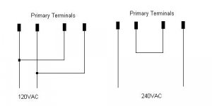
More often than not, if you have 4 primary terminals in a row, it will wind up being something like this:
Attachments
Thanks leadbelly,
I've an array/socket with 8 slots, and 2 "U" shaped and brass colored "jumpers" which connects 2 pairs of slots.
The wires from the tranny goes to this white plastic multisocket underside the mainboard and couldn't yet locate them.
Another issue is the chip which is said to store the "REF FREQUENCY" and matches this stored value with the actual mains frequency, in order to light the unit only if they match...
mumble, mumble...
Stefano
seppstefano said:Another issue is the chip which is said to store the "REF FREQUENCY" and matches this stored value with the actual mains frequency, in order to light the unit only if they match...
Are you sure about this? It sounds like nonsense to me.
Sadly I got some feedback that this practice is also used by Krell, ML, in order to "close" markets...
BS!!! But, as components are there and we have a classic PSU (the tranny, 2 rectifier bridges, caps...)... so I'm wondering where, following logic, might this damned chip play a role???
Stefano
BS!!! But, as components are there
and we have a classic PSU (the tranny, 2 rectifier bridges, caps...)... so I'm wondering where, following logic, might this damned chip play a role???Stefano
Hi Kuad,
sadly the project is still asleep...
Easy and expensive approach: buy a voltage regenerator (like psaudio) to generate a custom 120VAC/60Hz;
DIY approach: connect a sinusoidal signal generator at 60Hz to a robust power amp able to surge lots of current and use this setup as a "mains supply".
Taleban approach: skip the whole PSU and mains section, and replace with a custom external one.
This said, I've still to find time to proceed on this
Stefano
The other alternative is to do what many people have done with Krells - find where the CPU is getting a feed of the mains frequency from (usually the secondaries via some opto isolator), and connect a small oscillator here that will oscillate at about 60hz. A 555 would probably do it.
Stefano, thanks for answer. Have you tryied simplest thing I mean connect CD transfort to simplest 230V to 120V power inverter ?
Have you located which jumpers are connected to primaries of power transformer ? There are 8 jumpers and 6 pins on transformer primary voltages side...
Have you located which jumpers are connected to primaries of power transformer ? There are 8 jumpers and 6 pins on transformer primary voltages side...
jaycee said:The other alternative is to do what many people have done with Krells - find where the CPU is getting a feed of the mains frequency from (usually the secondaries via some opto isolator), and connect a small oscillator here that will oscillate at about 60hz. A 555 would probably do it.
Yes, there is optoisolator HP 6N139 connected with resistors and zener diode to power input. Maybe I can connect 60Hz generator to it ?! Do you have schema of some 60Hz generator ?
jaycee said:The other alternative is to do what many people have done with Krells - find where the CPU is getting a feed of the mains frequency from (usually the secondaries via some opto isolator), and connect a small oscillator here that will oscillate at about 60hz. A 555 would probably do it.
Ok. I found what you meant by 555 ;-)
I made some fast simulation of 60HZ oscillator and it works good. Thanks.
Attachments
- Status
- This old topic is closed. If you want to reopen this topic, contact a moderator using the "Report Post" button.
- Home
- Amplifiers
- Solid State
- How to feed a 2nd hand Proceed with different mains voltage?