Banned
Joined 2002
")
Banned
Joined 2002
Personally, if the amp were to be used with lower impedance speakers as in many MTMs today, and subwoofers the voltage used should be reduced for the 4 transistor board if you want to be cautious since SOA can vary from device to device. But is that a good compromise? I say no.
By simply adding at least one more pair of output transistors, the output stage remains quite close to the original. When you consider the additional cost of a couple of pairs of outputs over the total cost of the amp it's really minute. What do you gain, higher rail voltages giving you higher power and headroom and a safety factor.
There's another thread discussing the equivalency of plastic versus metal output transistors and I gather that it take three plastics to two metal outputs.
I'll pass on the 4 output version. It is not good engineering IMHO.
The 10 might be overkill but it needs more than 4.
First of all I Okayed this thread to Jason because someone out there might find the 4 transistor version useful.
Secondly, before anybody decides if a 4 transistor version is good engineering or not, I have a little background regarding the design.
1) The big 10 transistor version was designed for full range or the bass channels in an active speaker, using rail voltages above the original level; I aim for +-75V.
2) The smaller version was designed for small speakers and the midrange and tweeter channels in an active system. The rails would be slightly lower then the original, say +-53V.
In general the 4 transistor version will be ok for full range use with rails of about +-50V or so, but the protection circuit needs to be redesigned to make sure that the transistors will not be damaged if the output is shorted. If you want an equivalent circuit to the original I’m pretty sure that 3 parallel plastic devises will do the job nicely.
On a slightly different note, I don’t think it’s polite or very helpful to comment on the level of engineering before knowing the reasons for a design. Clearly no one could, but this is the reason why I was a bit reluctant in releasing the design for a group buy in the first place.
Now you know, so I’ll leave you alone to decide what to do.
\Jens
Banned
Joined 2002
For me 10 is over kill way to much power or money for me to build. But 4 is perfect for any sub that i would be able to listen to and handle with out going deaf. Personally 4 transistors is to much but should be good enough to get good results with the distortion level low.
Second I like these small amps there perfect for a compact speaker or a nice small powered speaker : O )
Second I like these small amps there perfect for a compact speaker or a nice small powered speaker : O )
Keep this in mind. Jens also sees that the amp is good for a little over 50 volts or around 50 and that is what I eluded to. Why is that significant? Consider the power supply capacitors and what voltage ratings they come in generally. 50 volts is available but for long term reliability, it is not recommended that caps are used at the rated voltage since if you happen to have a higher than normal line voltage in your area that could be exceeded easily. What's the next step? It's over 60 volts for sure, higher voltage ones also generally have lower ESR too.. And that's the ones you should use. Now comes the issue, if the caps and everything else on the design is rated for those higher voltages, might as well use it especially if all it will take is two extra output transistors and a few resistors. The cost of the transformer will be the same since they are generally priced by VA ratings.
Just going by experience. You've gained a lot more power too for very little money ( Voltage Squared) and you've gained long term reliability. Since you're using this for subs, remember that at low frequencies there is a lot of relected complex impedances from subs and they are not purely resistive. This also necessitates a strong output section for the complex impedances. At the high rail voltages Jens intended to use for subs, the 10 transistor package is NOT overkill but prudence.
Just going by experience. You've gained a lot more power too for very little money ( Voltage Squared) and you've gained long term reliability. Since you're using this for subs, remember that at low frequencies there is a lot of relected complex impedances from subs and they are not purely resistive. This also necessitates a strong output section for the complex impedances. At the high rail voltages Jens intended to use for subs, the 10 transistor package is NOT overkill but prudence.
Banned
Joined 2002
jens I am sorry if you were offended by my saying it is not good engineering. I was just pointing out that much more was to be gained by simply adding another pair of outputs and the extra cost of doing so would essentially be just those components alone.
How about redesigning it for 6. The redesign is very well done and this 6 transistor board could become a classic in a sense.
If a 6 transistor was offered, I'd be in for 2.
How about redesigning it for 6. The redesign is very well done and this 6 transistor board could become a classic in a sense.
If a 6 transistor was offered, I'd be in for 2.
Banned
Joined 2002

You may look at the power capabillity of output stages compared to rated power in 8 ohm of commercial amplifiers.
I did that, (did it way too long, actually), i like numbers.
Most commercial amplifiers have a 4 to 6 ratio, only the very pricy ones go deep.
ML at 12 with class AB amps.
To me it makes more sense too to build an amplifier with abundant output devices, such an amplifier can drive more uncommon speakers.
More important, Class A bias can be set a lot higher, i think any decent amplifier should go 5 watts class A minimum.
But, if you think 10 is OK for the extended Leach, then 4 is OK for this one.
53 Volts will deliver between 100 and 125 in 8.
With regular 150W output devices as the 1302/3281 you have a ratio of 4.8 to 6.
Go for the 230 watt MJL's Jens mentioned on the extended leach thread and the numbers are like 7.4 - 9.2
For a commercial amplifier that would be really impressive output stage numbers.
The Toshiba's i am going to use for Jens's extended Leach boards were used in the +$15.000 Luxman M07.
I have 50 of them, if i am not content with 10 in parallel i will need to buy Delta-Audio extension boards.
The M07 used 6 of those devices for a nominal 100w/8, and had a large portion class A use.
The M07 was the successor of the very succesfull Luxman M05.
Dieter Burmester used 8 per channel in his 850 mono amplifiers, but that were fully symmetrical amps.(and pricy)
i know, i am crazy.
I am out of here, i've got no business on this thread.
4-6-10 transistors
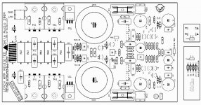
Hi Jens, in this thread :redesign of leach amp pcb for integrated TO-247 output devices, post 130 you placed a design what is my preferred design( because it fits on my heatsink.)
Here you made a little more space between the driver and power stage.
But I will wait and see what is coming out the smaller discussion.
Greetings, Loek
- Status
- This old topic is closed. If you want to reopen this topic, contact a moderator using the "Report Post" button.
- Home
- Amplifiers
- Solid State
- Smaller Leach Amp V1