The way i see a transistor is as a resistor with a variable resistance depending on the voltage at the base.
In that sense the power capability depends on the temperature of the transistor, which gives a margin till the transistor core reaches the breakdown temperature.
Its resistance determines the voltage drop from collector to emitter, Vce.
A high resistance means high Vce, a high current through a high resistance means high dissipation, means higher core temperature.
Both parameters too high and max temperature is exceeded and the transistor dies.
Now if you keep the temperature of the transistor low, the device can handle more heat for certain time periods before it fries.
And if the current going through it does this for a short period of time, the transistor is able too cool down before it is thermally attacked again.
That is why transistors handle more current for shorter periods at the same Vce value(resistor value).
If the interval is twice as short the current can be higher because at the end of the time interval the transistor die can cool down again.
So, if you stay at a safe temperature for the transistors by cooling them decently with proper heatsinks and assume they will stay below the 50% temperature SOA line they will live if at any frequency currents are not too high for a certain interval.
That currents do not exceed the limit for certain durations is what i've shown in the previous posting by expressing frequencies in time intervals, and checking how high currents can be for a certain voltage drop over the transistors collector to emitter.
The Leach amplifier has a built-in current limiting circuit that reduces voltage level to the driver stage if the output current exceeds the maximum acceptable.
Under normal operation parameters a 6 device Leach can handle a 64 Vdc PS easily.
A lot better than a number of commercial amplifiers from the past, i could give you a number of examples.
I posted a picture of a protection circuit some time ago, that compares output voltage and output current.
If a combination of high Vce and high current exceeds the level that is acceptable the circuit triggers a relay to shut the output down.
imo, any BJT amplifier output stage can be killed, i would never use one without protection.
Unless you desire to build an amplifier that is able to drive the worst loudspeaker under tropical conditions, but then you are thinking of the old Thresholds, and the K-brand.
If you use a normal loudspeaker on the small Leach the amplifier has plenty reserves with 6 output devices.
Use horrible low impedance monsters and you should look at other designs with much higher device numbers.
I am building the Leach with 10 because it will drive Quad ESL's, which has a 2.4 Ohms impedance at low frequency level.
A 6 device Leach with such high voltage would be suicide on those loudspeakers.
If i cant get the vented heat tunnels cool enough to go deep in class A i'll add another 10 Toshiba 1302/3281.
But the Leach amplifier for me is a nice project to see how much i can tweak out of it with different settings, different devices and biased heavilly.
Hi Jacco,
I bought some 6 trans boards and never built them so i bought some 12 transistor borads recently and have been reading this thread looking for inspiration and idea on how to build it.
I like your plan to build balanced, class A and regulated supplies, did your project ever get of the ground? Im curious if its worth the extra effort for this amp.
Its probably time I built some regulated power supplies and thinking of doing a pcb which Ive never done before and see how this thing sounds heavily biased.
Hi Luke,
I too bought the six boards too from this buy and after a number years I am just finishing the case and hard wiring etc ready to go live as they say. God I hope that I don't let any smoke out!!!
Anyway I have ended up using Bob Ellis regulated boards for the front end set at approx +/- 58 volts and output will be fed with approx +/- 54 - 56 volts. I just added extra windings to the transformers to get the extra voltage to the regulators. I am hoping that as the output from the transformer varies with load that the front end supply will remain stable regardless of what the output supply is doing.
If you want I can post some pic's of where I am up too.
I have also ordered four boards of the 12 version mainly because I have 19 of the output transistors left from the six boards (if no smoke appears of course) and I thought I would put them to good use and maybe get a 5.1 set up going fed by a HTPC!!!
Anyway it has been a great learning experience for me and if I can help just give me an email etc.
Cheers
Ian
Hi Ian,
better late than never, some of my projects drag on a bit, but I usually get there with one or two exceptions. Post pics and show us what youve done.
So of the 6 boards you bought how many channels have you built, Im kind lost as to why you want another two for 5.1?
I will probably regulate teh back end as well, listened to a ML No331 and decided regulation is worht a crack.
Im thinking about a media player cos I dont want to spend the bucks on a HTPC, whats the benefit of a pc over media player?
Good luck.
Leach Amp progress.
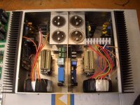
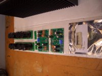
Hi Luke here is the photo's of progress so far. Hopefully it spurs you and others into action so I have someone to bounce questions off when it comes to switch on etc.
P.S. you might notice that there is my other project to the LHS. I am calling this the purest side of my thinking. i.e. Zen9, symetrical B1, rear loaded horns and TT!!!
Hope you enjoy.
Ian
Attachments
Hi Luke,
Hopefully it will live up to my expectations and by all accounts it should be a good one. (I will have to build some new speakers to go with it though).
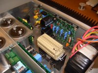
The regulator is the one from Jens and Bob Ellis. It is intended as a +/- 15volt supply but with some alterations will go to 75 volts.
I am trying to upload the schematic but the file is too big so I am having dificulties.
The heat sinks were not that exspensive if I remember correctly. But I will add that as someone commented on the new thread these are not cheap amps to build. (Especially in NZ) I would have spent up to 1k on this one (mostly freight I mite add). And this has probably added to the length of time it has taken also.
But it is a hobby remember!!!!! (I keep telling myself)
Ian
Hopefully it will live up to my expectations and by all accounts it should be a good one. (I will have to build some new speakers to go with it though).
The regulator is the one from Jens and Bob Ellis. It is intended as a +/- 15volt supply but with some alterations will go to 75 volts.
I am trying to upload the schematic but the file is too big so I am having dificulties.
The heat sinks were not that exspensive if I remember correctly. But I will add that as someone commented on the new thread these are not cheap amps to build. (Especially in NZ) I would have spent up to 1k on this one (mostly freight I mite add). And this has probably added to the length of time it has taken also.
But it is a hobby remember!!!!! (I keep telling myself)
Ian
")
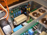
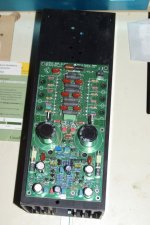
Loboone - I see Mosfet outputs in your picture but the circuit was designed for bipolars. Did you change the Vbe multiplier and gate stoppers? I have a set of boards stuffed but not tested for IRFP outputs, using a ZVN3310 in the Vgs multiplier to get the required bias voltage and swapped in 221R for the gate stoppers as the 3.3R or 10R used for bipolars won't help much.
Just trying to help keep the magic smoke in the packages, in case someone inexperienced sees your pictures and tries mosfet outputs without making changes.
Edit: Anyone wanting the regulator schematic and supporting documentation just email me. I've got some time on my hands and might be coaxed into another group buy if there is enough interest.
Last edited:
Hi Luke,
Hopefully it will live up to my expectations and by all accounts it should be a good one. (I will have to build some new speakers to go with it though).
The regulator is the one from Jens and Bob Ellis. It is intended as a +/- 15volt supply but with some alterations will go to 75 volts.
I am trying to upload the schematic but the file is too big so I am having dificulties.
The heat sinks were not that exspensive if I remember correctly. But I will add that as someone commented on the new thread these are not cheap amps to build. (Especially in NZ) I would have spent up to 1k on this one (mostly freight I mite add). And this has probably added to the length of time it has taken also.
But it is a hobby remember!!!!! (I keep telling myself)
Ian
Im finding that anything complex in design is not cheap and higher power levels need more outputs bigger transformers etc.
So is this using mosfets on the output, Ive never heard of this configuration on a leach.
Fantastic Loboone.
Yes - Hobby or obsession
Would be interesting to have someone do a writeup of their subjective opinion of the difference between regulated and non regulated frontend.
Mine sound good as is - but maybe ...
yes and power stage as well would be nice to hear about.
Hi all,
Sorry for the confusion but the mosfets etc to the left of the Leach are for my other (some may say dark side) of my hobby. Parts and boards for ZEN9 amp and symetrical supply B1 pre-amp.
I was just trying to show off the fact that I have some Power J-Fet LU1014
as I believe they are somewhat hard to come by!!
So if you all are thinking that I am even close to the level of expertise that you good people are you are sadly mistaken. I am I true believer in if it aint broken (or works perfectly well) why try and re invent the wheel. So the Leach will be as per plans accept for the regulated front end.
Thankyou all for the nice comments though. I would be more happy to answer any questions with regards to the amp etc.
I'll keep you all updated.
Ian
I am just getting around to the Small Leach build from 5 years ago and need some advice to proceed further. The pcb is stuffed except for the output transistors. Bob Ellis and AndrewT have helped with building a regulated power supply. Now the project is to the point of connecting the pieces together for testing, but before that occurs, some advice is needed for the enclosure. I am a woodworker so I was leaning towards a wood enclosure.
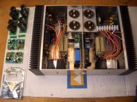
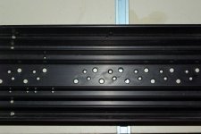
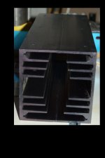
The heatsinks were obtained from ApexJr a few years ago--a pair of sinks 2.3 x 4.6 x 12.5 inches which can form a tunnel 4.6 x 4.6 as shown in the photos below. The mounting plane of the sink is 4.5mm or .175 inches thick. I have no idea of the exact cooling capacity of the sinks or even if an estimate of their cooling capacity is possible.
The enclosure, if built with the tunnel, would be too high at 12.5 inches. Would anyone hazard an opinion if the sinks would be adequate to cool the unit if they were to be cut down to about 8.5 inches. The tunnel would be oriented vertically. A muffin fan is available in the tunnel size if 12 VDC can be obtained to feed it to help augment the heatsink cooling. But whether a fan is advisable or not is another question.
The output transistors positionally mount on top of the heavier and deeper fins of the sink. If you see any obvious problems with the pcb feel free to comment as well.
Attachments
Another project for you - find a temperature sensitive fan controller circuit. Rod elliot has one and there are a few here, including a two speed controller. Mount the sinks horizontally and have a fan kick on only if they get too warm. Burying the fan inside a wooden case will help keep it quieter, although it probably would be slightly more efficient sucking air through the sinks.
I have four channels of Leach amp (V4.5 on Leach boards) on those sinks mounted horizontally running at ~100 mA bias each for 45W. The amp gets warm but not hot in normal use. Although I haven't really driven it hard I hadn't connected without a fan until recently. I'm using a 10W 120VAC fan - I don't remember its flow rating, but I cranked the bias up to 750 mA/channel (~330W) and the output end of the sink gets to about 50C (after an hour I can put my fingers on it for more than 10 seconds, but it is hot). The amp is doing double duty, making music and giving my bhut jalokia and other hot pepper seedlings nice warm days in my indoor hot house. Another month or so I'll turn the bias back down when it warms up enough to move the plants outside.
I have four channels of Leach amp (V4.5 on Leach boards) on those sinks mounted horizontally running at ~100 mA bias each for 45W. The amp gets warm but not hot in normal use. Although I haven't really driven it hard I hadn't connected without a fan until recently. I'm using a 10W 120VAC fan - I don't remember its flow rating, but I cranked the bias up to 750 mA/channel (~330W) and the output end of the sink gets to about 50C (after an hour I can put my fingers on it for more than 10 seconds, but it is hot). The amp is doing double duty, making music and giving my bhut jalokia and other hot pepper seedlings nice warm days in my indoor hot house. Another month or so I'll turn the bias back down when it warms up enough to move the plants outside.
The challenge would be to balance the size of heatsink with optimal bias vs temperature. With the thermal compensation diode feeding a fan controller circuit from ESP site that could make this automatic is definitely worth the look. This would be used to control fan speed.
Vertical sink tunnels are best. They need the least power assistance to achieve a certain cooling ability.
Blowing the sink is more efficient than sucking.
Blowing also exposes the fan motor to cooler temperature.
An early Pass had blown vertical sinks. Was it the *40?
Three temp switches on the sink would be great. all off = fan off.
first on = slow fan. Second on = fast(er) fan. Third = power down.
or use a variable as Bob suggests, but still fit a power down switch, or at least a loud/bright alarm.
BTW,
the emitter resistor value and the PSU voltage determine the amplifier Pq.
Watch for blowing fuses with those on board capacitors. 4700uF and +-58Vdc needs a long current duration to charge up.
There is space for 15mF, but that is virtually un-fuse-able.
Last edited:
That Pass amp was the A75.
I was thinking a multi speed fan, too. Seems easier to design/build a controller to me. Good idea for a cool down after shut down.
The Hafler DH500 uses an AC fan and a couple of 300R/7W resistors in series. As temperature rises thermal switches sequentially close, increasing the fan speed. With 600R in series, the fan is virtually silent. You could add a lower temperature switch to shut off the fan completely at lower temperatures. Not the most efficient way to reduce the speed of an induction motor, but it does the job.
Thanks for all the help guys. I have my homework. I'll have a look at the ESP solution. The consensus as I see it, do not cut the heatsinks shorter.
The heatsink tunnel is more efficient vertically but fan-driven horizontal orientation is just fine especiallyif Bob can run 4 channels off these sinks instead of the 2 that I`m using. I don`t have a greenhouse to heat either.
Andrew, the emitter resistors are 0.47., the transformer is 39.8-0-39.8 so it should be about 56V at the PSU.
- Status
- This old topic is closed. If you want to reopen this topic, contact a moderator using the "Report Post" button.
- Home
- Amplifiers
- Solid State
- Smaller Leach Amp V1