Hi Terry,
something you said about your bias wandering because you set it up with a cold heatsink. This does not ring true and thinking back to what was discussed here on temperature compensation makes me wonder if the 4 diodes are not doing the right amount of compensation.
What should happen is that as the junctions heat their surroundings is that the junction voltage drops as the temperature rises. The compensator will adjust the voltage down to bring the bias back to set point or acceptably close. This tends to be over the medium term, there will be short term errors when junction temp has just risen and the compensator is still cooler but it will catch up and during this delay there will be excess bias and similarly as the junction cools but because the heatsink cools slowly and keeps heat in both the junction and the compensator then the delay on cooling causes only a slight underbiasing. ( this seems to me just fortunate).
Can you do something for us?
Can you try cycling the heatsink over a range of temps and after allowing things to stabilise measure your bias voltage to see if yours are over compensating or under compensating.
This will give some amunition to try and track down your and maybe a design problem.
Eh Andrew,
I thought Terry's description sounded right. Initially left Vq was 40mV, right Vq was 70mV. Right channel was facing the cool air. So the reduced temp on the right channel VBE diodes would cause the compensator to increase Vq.
So what is the problem?
PS: Terry, I am not saying you shouldn't do what AndrewT asked for. The data after all, could be valuable. Heheh.
On a slightly different note, setting Vq is not a big deal. What's more important is getting the design right so that the need to set Vq frequently is removed. Hence the joy of DIY experimentation.
If anything, Leach's four diodes should overcompensate, so the bias shouldn't have drifted to 70mA. Leach said three diodes would work, but he used four so that the leads would come out on the same side of the heat sink, and didn't have trouble with that many.
Biasing by the current method is harder, since the current drifts more and therefore it is harder to hit a target. If there is any oscillation going on, temperature rise may not be due to DC bias. It may also be good to twist the probe leads together to keep from picking up stray currents, like from the transformer or power line, although this wouldn't be DC.
Biasing by the current method is harder, since the current drifts more and therefore it is harder to hit a target. If there is any oscillation going on, temperature rise may not be due to DC bias. It may also be good to twist the probe leads together to keep from picking up stray currents, like from the transformer or power line, although this wouldn't be DC.
AndrewT said:Hi Terry,
something you said about your bias wandering because you set it up with a cold heatsink. This does not ring true and thinking back to what was discussed here on temperature compensation makes me wonder if the 4 diodes are not doing the right amount of compensation.
What should happen is that as the junctions heat their surroundings is that the junction voltage drops as the temperature rises. The compensator will adjust the voltage down to bring the bias back to set point or acceptably close. This tends to be over the medium term, there will be short term errors when junction temp has just risen and the compensator is still cooler but it will catch up and during this delay there will be excess bias and similarly as the junction cools but because the heatsink cools slowly and keeps heat in both the junction and the compensator then the delay on cooling causes only a slight underbiasing. ( this seems to me just fortunate).
Can you do something for us?
Can you try cycling the heatsink over a range of temps and after allowing things to stabilise measure your bias voltage to see if yours are over compensating or under compensating.
This will give some amunition to try and track down your and maybe a design problem.
Hi Andrew,
I was only guessing about the heat issue. I don't really know why I got such a big difference in bias readings the second time I checked them. It is possible that i just didn't wait long enough for the amp to settle the first time I set the bias using the current adjustment. I did take about an hour to do it but probably only waited 10 minutes after the last adjustment. I have a problem with the meter I used for that. It has a sleep mode that shuts it off after a time of not being touched. When this happens it opens the connection and the current stops flowing. Each time this happens you have to start over. Another reason to use the voltage reading instead of the current reading I suppose.
I don't have a clue how to "cycle" the heatsinks over a range. I think before I try re-adjusting things I will add some wires to the emitter resistors so that I don't have to stick my probes down into that area of the amp again. Twice when I was attempting to bias my Krell I shorted out something and blew a whole bank of output transistors. I don't want that to happen here. It is playing very nicely right now and I'd like to keep it that way. Do you guys have any idea if having test wires leading away from the emitters to some sort of jack will effect the way the amp reacts? If it will have no effect then I will go ahead and add them.
Thanks, Terry
still4given said:
Twice when I was attempting to bias my Krell I shorted out something and blew a whole bank of output transistors.
Been there, done that with an A75.

I guess it is a credit to my power supply that I was able to take out 20 3 watt source resistors, too. They went like popcorn even after I yanked the plug out. My son was amused watching the sparks fly.
Hi Terry-
Another approach that might be useful, and more temporary, would be to pick up a set of probes for your meter that have little retractable hooks, rather then straight tips. I got a set for a couple bucks.
You could hook them to your emitter resistors and run them out of the case. This way there is no perminent installation, but you can leave them there as long as you want to get the bais set, then unclip them.
Hi Terry,
the two leads/test points are very low impedance and will be extremely resistant to interference.
It should be safe to extend them to the case rear panel or test loops hanging out the bottom through an insulating mounting. You can hook a pair of test probes onto the loops to carry out voltage checks hands off.
Can you describe again the conditions that come before and after the 40mV/70mV bias readings? and the adjustment rotation required to correct it? These are not DC offset?
BrianDonegan said:Hi Terry-
Another approach that might be useful, and more temporary, would be to pick up a set of probes for your meter that have little retractable hooks, rather then straight tips. I got a set for a couple bucks.
You could hook them to your emitter resistors and run them out of the case. This way there is no perminent installation, but you can leave them there as long as you want to get the bais set, then unclip them.
Hi Brian,
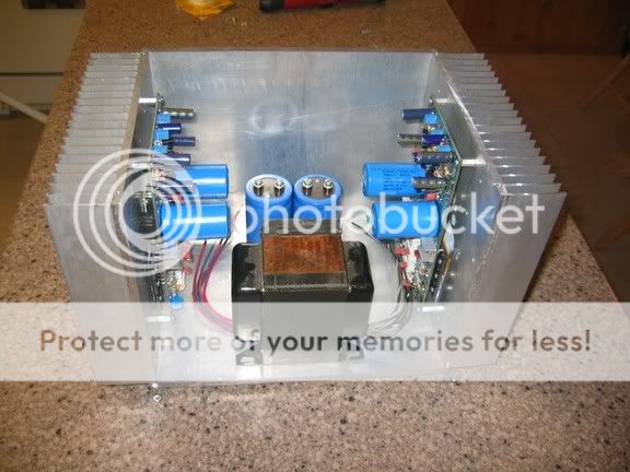
That type of clip is what I used. The problem is getting them attached without touching anything else. If you look in the pic you can see how deep into the case those resistors are. I was able to manage it but it was scary. The caps that are right next to the resistors carry rail voltage. One little slip and POW, you are replacing parts. I would rather take the time to drain all the caps and solder in a couple of leads that can stay there than to keep reaching down in there with probes.
Can you describe again the conditions that come before and after the 40mV/70mV bias readings? and the adjustment rotation required to correct it? These are not DC offset?
I set the current by disconnecting the + rail lead ( I didn't use rail fuses, only a main fuse) and hooked my multi-meter in between and set it to mA. I turned the pot clockwise to raise mA and counterclockwise to lower it. I brought it up to 100mA and let it run for a while. Then re-adjusted it and let it run longer. then checked it again. Once it would stay within a couple of mA of 100 I stopped and hooked up the other channel and went through the same thing. It was after this that some of you guys said it should be biased higher because Leach's amp had only 4 outputs and this one has 6. this time I decided to use the voltage drop to set it rather than have to disconnect everything and drain the filter caps and all that entailed. That is when I noticed that I had 40mV drop on the left channel and 70mV on the right. I had noticed that the right heatsink felt warmer than the left. I had had the amp running for a couple of hours at least. I did find it easier to adjust the voltage drop and it was definitely less sensitive. After about 30 minutes I was able to get it to settle down to 54.8V drop over the pair of resistors. Because of the delicate nature of attaching the probes I didn't check each pair to see if they were the same. I only used one pair per channel.
It sounds fine to me now and the heatsink are both running the same temp, about 40c.
Blessings, Terry
Arius said:Haha, I really loved Jen's last post. Terry's amp is working fine now after all.
I'm fiddling with Vbias circuitry now. No results yet.
Happy DIY-ing.
i second that! there is a wealth of information now accumulated in this thread!
nice one jens,
more leach amps to come!
Hi Terry,
after hearing those others telling me to shut up. I did. But I cannot stand back and keep quiet when I am concerned for your amp and the way it is behaving.
I think they did not pick up on the point I was trying to make and your second description confirmed to me that your amp may be thermally under compensated .
It appears that you set the output current bias when the heatsink was slightly cooler than normal ambient. When the amp was repositioned the heatsink and semis warmed to their new surroundings and the bias increased by about 75%. This should not happen. It resulted in a significant increase in temperature in one side of your heatsinks. I think it is the large size of your heatsinks and case that possibly saved your amp from becoming thermally unstable. My reasoning is that the extra output stage heat was dissipated by the large sinks, otherwise the Vbe would have dropped even further and the bias would have kept increasing. I cannot tell when or if that would have reached thermal equilibrium.
I am left wondering what if the sinks had been smaller? Could your amp overheat? What if you moved your amp to beside a radiator in mid winter?
I would like to reopen the discussion on which way round the diodes should be. Thermal comp diodes in contact with the output heatsink or PCB in contact and diodes facing the main PCB?
AndrewT,
No one asked you to shut up – I asked for Terry to be left alone to do things in his own time!
I have placed the thermal diodes on the top of the PCB and used a thermal pad between the diode PCB and the heatsink. This has so far worked ok and I have not seen any thermal instability yet.
I tested the 10-transistor amp at 300W into 4 ohm. I let it heat until the heat sink was too warm to touch. I removed the signal and watched how the bias current fell to the initial setting. What more can I do to test if there is a problem?
Terry don’t mess with with loose wires in your amp anymore, I’d hate for you to burn something. I have the 10-transistor prototype sitting on a heat sink in my shop. I can easily test different settings on this if it helps clear things up.
Let me know
\Jens
Hello Andrew,
Please, allow me to second what Jens said - nobody asked you to shut up. I'm sorry if my post conveyed the wrong meaning.
Your contributions and comments are appreciated. I hope that clears things up.
OK back to the amp - you brought up an interesting question. Positioning/mounting of the VBE diodes. Dr Leach had his diodes INSIDE the heatsink while Jens had his in contact with the heatsink through the thermal resistance of the PCB (and thermal pad too).
Jens said he didn't find any issues with that setup. Jens, may I propose an experiment if you are willing to oblige? Could you heat up your heatsink with an EXTERNAL heat source and watch for any drift in Vq? Just to see if there's any thermal lag (other than the heatsink mass lagging the output junction temps). If you think it's pointless, I'll understand. EF stages are after all, the hardest to bias properly and have the highest idle dissipation. I'm just being academic, as long as it sounds good however it is, it's ok.
Thanks.
Hi,
Correct me if I am wrong.
The thermal compensator for controlling the bias should keep the bias current the same or close to the same when the drive and output stages are at thermal equilibrium. I also think that the short term errors in controlling the bias current by the conventional Vbe multiplier will lead to slight to medium overbiasing when the temperatures are rising and as previously stated slight underbiasing when temperatures are falling.
A bias seting that is seen to return to normal after an extended period at high temperature does not fit my model stated above. Instead it indicates an increased bias current at elevated temperatures and, as with Still4given, a reduced bias current when temperatures are depressed artificially or by location.
I do not believe that is how the compensator should be designed to work. There is a greater chance (some more knowledgeable than me might state this more strongly) of thermal run away with a rising bias current with temperature particularly with small but normally adequate heatsinks.
The ideal thermal compensation circuit should track the temperature of the components that determine the bias current in the output stage. This can easily be done by means of a similar semiconductor as the one(es) being compensated.
In order to track "perfectly" the exact temperature of the output transistors in this amp the thermal diodes should be placed on top of one of the output transistors. (The small SMT diode PCB will work here) but this calls for wires to connect the thermal diodes. I wanted to keep the layout as tidy as possible and thus opted for the solution with the larger PCB for the thermal diodes to be mounted on top of the heat sink. Some might think that the new thermal track devises from ONSEMI are perfect for the job, they might be, I think it is possible to test them in the exciting PCB without changing too much.
I know that the ASKA amp uses a TO126 transistor mounted directly on top of one of the outputs. This is a good solution for smaller PCBs where the required length of wire is short. For this layout I thought it to be untidy and opted for the current solution. I also knew that some might find this solution inadequate and thus provided the SMT solution. A third option could be to mount the thermal diodes as the original design.
I don’t think there is any amp that has perfect thermal tracking. The ASKA might come close, but as I have never had one of these amps I can’t confirm this. In any case this PCB was made in a way I felt had ok thermal stability – what others think is not really of any concern to me. You are welcome to redesign the thermal tracking solution to fit your needs (It not possible to satisfy everyone - so I'm not going to try); I will choose one of the two systems provided with the amp – time will tell what I find best in the end.
\Jens
Hi Jens,
Your design follows very closely with that of Leach and on that basis cannot be faulted. You have also given us options to increase flexibility to cover a wider range of component choices, again commendable.
I (we?) would like to hear from others (so far only Jens & Still4given) on how well the diodes in various configurations track the output temperatures and control the bias.
Does anyone have comment on what the compensator should be achieving in controlling (holding) the bias at different equilibrium temperatures.
Hi Guys,
Sorry to have started a ruckus over my not doing things properly. I have really done it now. I took my amp to a friend to have him give it a listen and when I plugged it in and turned it on I saw a flash and then the left channel went out. I shut it down and brought it home. I checked it with nothing connected and had -57VDC on the left channel output.
So this morning I took it apart and discovered that the insulator I had used for the small heatsink for T22 had failed and it shorted out to the ground. So I began doing some side by side comparisons between the two channels. The rail voltage was showing up in too many places on the bad channel so I disconnected the VCC and just ran the regulated voltage to the front end. Everything checked out pretty even until I reached T8 and T14. The collector on T8 read +2.6V, while the collector on T14 read only -.303V. That threw everything off from there on out. I replaced both transistors but to no avail. Same problem.
I started marking the voltages on the schematic for both channels but before I was able to finish the good channel started reading funny. Does it hurt to run these amps without the power to the back end? I tried to be very careful when probing but I may have shorted something because now the good channel doesn't read correctly and it's showing about 2v offset at the output. Before I started all of this it read 8mV offset.
What a hobby
Anyway, I someone has an idea of what is causing the difference between T8 and T14 it will give me a place to start.
Thanks, Terry
So this morning I took it apart and discovered that the insulator I had used for the small heatsink for T22 had failed and it shorted out to the ground.
hi terry,
i anticipated that somehow, what i did with my board was to place double insulation! once under the to220's and another under the heatsink. i used silicon pads, the type that don't require silicon grease!
some folks might frown on this, but i don't care. i have had my share of amplifier failures and i am not taking chances!
you may have to replace transistors from driver all the way up to the ltp's. one time, i even had to replace a zener. just be patient and take your time, remember, haste makes wastes!
lesson learned? never loan out your new amp to friends, they don't care! lolz! maybe later, after a while!
regards.

- Status
- This old topic is closed. If you want to reopen this topic, contact a moderator using the "Report Post" button.
- Home
- Amplifiers
- Solid State
- Smaller Leach Amp V1