Sijosae,
VERY neat idea! I haven't seen it before.
I think it will clearly improve on the Vb stability over the left side diagram.
I have a few questions, though. With the high quality of the 317 as current source, most likely the current through the 317 is more stable than the current through the transistor. The current through the transistor is still depending on variations in Vbe, temperature and even voltage.
So, if your aim is a very constant, high impedance current source, the 317 alone is probably better then in combination with the transistor.
Just some thoughts.
Jan Didden
sijosae said:e.g. LM7824 --> as a 24V zener diode.
I'm hardly an expert, but isn't the LM7824 both more expensive and much noisier than a zener?
sijosae said:I just tested this new CCS as follows.
V+ : mA
1.86 : 0.000
2.41 : 0.533
2.86 : 1.236
3.05 : 1.243
3.61 : 1.249
4.50 : 1.250
6.93 : 1.251
10.63 : 1.255
12.39 : 1.256
14.79 : 1.257
(2N2222 - 500 ohm, LM317L - 300 ohm)
IMHO, it shows very good results.
OK, lets do a quick calculation. Between 4.50 and 14.79 volts, the current varies 7uA, that's a dynamic impedance of about 1.5 megohms. Pretty good indeed, surely better than the LED version.
But what is the variation in Vb with the same steps? That will tell you what is better, just the 317 or the 317+transistor.
Jan Didden
sijosae said:Thanks Jan Didden,
I completely agree with you.
Yes. I know the current through the LM317 is more stable.
However there is a lower limitation in the current. (datasheet of the LM317L)
In that case, current should be > 5 mA.
Indeed, you're more flexible this way. Good thinking.
Jan Didden
Interesting idea, Sijosae.
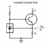
However, the voltage reference will always require a prescribed current from the collector source which will vary very slightly as the potential stress across the LM317 increases. Is this a good thing?
Another option might be to run the LM317 from another power rail (positive with respect the to the LED anode) and then run a resistor from this same rail to the emitter. Chosen correctly, this should compensate changes in Vbe with rising and falling voltage at the collector. This is an Elektor idea, incidentally, not my IP at all!
Cheers,
Hugh
Just a thought. Absolute accuracy on the ccs is not the most important thing with audio. Temp compensation is more important (within reason) and noise figures. Ultimately cost comes into play as well. The red led - transistor circuit is my fav and is very flexible. The delta V is not going to be much so is not that important. Temperature compensation is very good (mounted in thermal contact).
The LM317 has limits on supply voltage so it may require it's own supply. All told, a neat circuit though.
-Chris
The LM317 has limits on supply voltage so it may require it's own supply. All told, a neat circuit though.
-Chris
I introduce my previous test results for several CCSs.
http://www.headphoneamp.co.kr/bbs/zboard.php?id=diy_sijosae&no=211
I think, my test was not so accurate.
But it will be very informative.
http://www.headphoneamp.co.kr/bbs/zboard.php?id=diy_sijosae&no=211
I think, my test was not so accurate.
But it will be very informative.
ultima:
same for me. this one has worked great for MANY years.
same for me. this one has worked great for MANY years.
Ultima Thule said:Here is an accurate CCS with a voltage reference I have used several years with good results, and it don't get much better...
Cheers")
Zener diodes are inherently more noisy than band-gap references, the latter is used by the 317. It is fairly quiet as the classic 3-terminal regulators go, which cannot be said for the 78xx and especially for the 79xx series.
The circuit has three drawbacks:
1 - the breakdown voltage of the 371, which is about 40V or less, so that is as high as the input of the 317 can go. There is no such limitation on the transitor, however.
2 - It is not advisable to stabilise the 1.25V reference voltage developed on the base resistor with a capacitor, although this would be highly desirable. The transistor can also havea much higher bandwidth than the LM317 - do not take it's static condition as any indication of how good a current source it is - you need to remember that in an amp, the current source usually has (sometimes wildly) varying voltages on it, and in general the output impedance of the source (which sould be infinite for an ideal CCS) drops with rises in frequency (also some more complex problems may occur too). A capacitor between B and E would swamp out the miller capacitance of the transistor resulting in improved HF performance.
3 - current still depends on the Vbe of the transistor. This could be compensated for by the inclusion of a diode, or better still, a diode connected transistor in thermal contact with the CCS transistor in series with the 317 feedback leg.
- Status
- This old topic is closed. If you want to reopen this topic, contact a moderator using the "Report Post" button.
- Home
- Amplifiers
- Solid State
- New CCS Idea