It should be pointed out that a very simple supply discharge circuit may be made with only a very few parts.
If you use an SBS it will turn on two triacs, one for the positive supply, and one for the negative supply, with a single trigger part (the SBS). It can do this better than an SCR as the triac will trigger with either polarity signal at the gate in all four quadrants of operation.
So with the SBS you only need a resistor and a cap as the DC integrator, a series current limiter resistor feeding the SBS, and two triacs, that's it.
The intergrator cap will charge up to the firing voltage of the SBS, the SBS will go to a low voltage state, and the cap will discharge into the gates of the triacs, the series resistor will protect the gates from excessive gate current. The cap is usually around 10µF, the resistor forming the integrator is usually set to allow full power operation down to 8hz~10hz, and the series limiting resistor to the maximum gate current of the triacs. Because the 10µF cap can dump a pulse of several amps (when the SBS switches states), any triac may be used, you don't need a sensitive gate model.
Other than the triacs, only four parts required.
AndrewT said:Hi Workhorse,
No real conclusions yet, I have not completely written them out of my design arsenal.
You have been very thorough to find such an exceptional FET that does support your contention that this FET can stand a short term pulse better than BJT. Almost all the other FETs I have looked at are no better and usually worse than BJT in this respect.
You win that point.
Hi AndrewT,
Check out...
APT20M22LVR....Compare it with Largest METAL NPN AUDIO POWER BJT on earth..THE GREAT MJL21294
http://www.advancedpower.com/Communities/APT/Products/20M22LVR.PDF
http://www.onsemi.com/pub/Collateral/MJ21294.PDF
See the difference......APT20M22LVR 5A @100V @ DC....
whereas
MJ21294 3A @ 100V @DC + Second Breakdown Voltage as Free Gift

regards,
K a n w a r
Hi DJK,
It costs about just around...3.25 USD......
The main Gate drive Consideration is Qg...The Gate Charge which is only 290 nC....The 10nF gate capacitance isn't a restriction or harder to drive..when drived properly from push-pull drivers.....I have implemented them in my commercial products as well....
K a n w a r
AndrewT said:Hi Workhorse,
No real conclusions yet, I have not completely written them out of my design arsenal.
You have been very thorough to find such an exceptional FET that does support your contention that this FET can stand a short term pulse better than BJT. Almost all the other FETs I have looked at are no better and usually worse than BJT in this respect.
You win that point.
Hi AndrewT [T probably stands for Teacher isn't it]
Have you found any BJT to stand Still against APT30M85BVR yet, if yes than what's the name of that Beast....
K a n w a r
Hi Workhorse,
I told you way back that I would not fall into the trap of selecting an output device to meet your criteria.
I am not in the business of trying to develop an unburstable PA amp.
I will NOT be looking for an equivalent BJT.
What I have already accepted is that your selected FET does meet part of the claim that you made. i.e. to exceed the short term load increase by a factor larger than most quality BJTs can achieve. I did suggest that your FET might be a candidate for a Vrail cutoff switch but other respondents said Triacs do it better. So what use is this to me?
None of the foregoing, including your somewhat biased views, will ever convince me to start a new profession in designing and/or selling PA amps.
I am DIYist interested in quality music reproduction in the original meaning of HiFi - HIGH FIDELITY
have a good day.
AndrewT said:Hi Workhorse,
I told you way back that I would not fall into the trap of selecting an output device to meet your criteria.
I am not in the business of trying to develop an unburstable PA amp.
I will NOT be looking for an equivalent BJT.
What I have already accepted is that your selected FET does meet part of the claim that you made. i.e. to exceed the short term load increase by a factor larger than most quality BJTs can achieve. I did suggest that your FET might be a candidate for a Vrail cutoff switch but other respondents said Triacs do it better. So what use is this to me?
None of the foregoing, including your somewhat biased views, will ever convince me to start a new profession in designing and/or selling PA amps.
I am DIYist interested in quality music reproduction in the original meaning of HiFi - HIGH FIDELITY
have a good day.
Hi AndrewT,
I am not a Fisherman to through a TRAP in which you always Fall.....baby
Nor i am encouraging you to start a PA business...using mosfets...
If you aren't looking for equivalent BJT , then what is the meaning of Posting the matter of comparision with Mosfets...in your previous posts....you self -contradict yourself buddy...
I think all members are pure DIYers in their own respect....on this Forum.....interested in quality and simplicity at most attainable way around.....
You said that BJT and Mosfet have same comparable SOA,
BUT
I said Mosfet have Big SOA....which was true
I have only asked you ..if you had any BJT in your mind which exceeds that mosfet...that was the actual question..then where came in your mind all this phenomena of business + encouragement + diying...
Wishing you a good day,
K a n w a r
SOA question
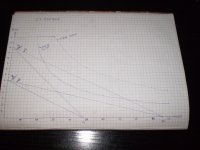
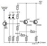
I have several questions about the SOA of the transistor. Supply voltage is + /-48V DC, amplifier is in class AB, two pairs of output transistor 2SK1058 and 2SJ162. I drew the SOA for two 2SK1058, so I am now interested in how to protect these transistors. Please note, each output transistor has a gate resistor of 220ohm and has a gate protective diodes (1N4148+ zener 12V).The source resistors are 0.22ohm 5W.I have no fuse in amplifier power supply. Still considering whether to use upc1237 or OMNI Protection as speaker protection. I found an interesting protection Protection system for power amplifiers - ELEKTOR.com | Electronics: Microcontrollers Embedded Audio Digital Analogue Test Measurement and http://www.linearaudio.nl/SOA-2.htm so I wonder how to set up protection.
What SOA I need to use, DC(TC 25 degrees), 100mS SOA or maybe DC(TC 75 degrees)?
Attachments
Hi,
your upper locus looks like it connects 12A to 96Vds.
This is the equivalent to a 4ohm reactive load for all combinations of reactance.
The 25degC SOA for DC is of no value to your assessment. When will the device Tc be at 25degC and you overload your amplifier? (only when you switch it on, after that Tc will be much warmer).
There is something wrong with the 100ms locus. It shows 400W @ Tc=75degC. This cannot be for 2pair.
I see it falls between the DC value and the 100ms value at worst case (highest power dissipation). This is OK for power.
It falls outside the current limit. 12A ref 7A. Are you using 2pair for 14Apk capability?
Normally FET outputs are not fitted with IV limiting.
They can dissipate lots of power even at high Vds, unlike BJTs.
The Zener + diode are a gate protection but this also limits the Vgs. Look at the Id vs Vds curves for your devices. A lower voltage Zener will act as a short circuit current limit that should allow the FET to survive until the Rail Fuses rupture.
What size of heatsink are you planning? What Ib are you planning?
What Tc are you planning?
These will determine the the de-rated SOAR for very short term overloading.
For longer term overloading the heatsink is liable to be very much hotter and the Tc for this condition must also be used for your de-rated SOAR as an alternative worst case operating condition.
Last edited:
Hi,
your upper locus looks like it connects 12A to 96Vds.
This is the equivalent to a 4ohm reactive load for all combinations of reactance.
The 25degC SOA for DC is of no value to your assessment. When will the device Tc be at 25degC and you overload your amplifier? (only when you switch it on, after that Tc will be much warmer).
There is something wrong with the 100ms locus. It shows 400W @ Tc=75degC. This cannot be for 2pair.
I see it falls between the DC value and the 100ms value at worst case (highest power dissipation). This is OK for power.
It falls outside the current limit. 12A ref 7A. Are you using 2pair for 14Apk capability?
Normally FET outputs are not fitted with IV limiting.
They can dissipate lots of power even at high Vds, unlike BJTs.
The Zener + diode are a gate protection but this also limits the Vgs. Look at the Id vs Vds curves for your devices. A lower voltage Zener will act as a short circuit current limit that should allow the FET to survive until the Rail Fuses rupture.
What size of heatsink are you planning? What Ib are you planning?
What Tc are you planning?
These will determine the the de-rated SOAR for very short term overloading.
For longer term overloading the heatsink is liable to be very much hotter and the Tc for this condition must also be used for your de-rated SOAR as an alternative worst case operating condition.
100 ms SOA is for transistors temperature of 25 degrees, for one transistor 100ms SOA is 100V 2A, for two 2SK1058 100V 4A, it is 400W at Tc=25degC.
With rail power supply of +/-48V DC, I will use for one rail 2*2SK1058 and for other rail(negative one) 2*2SJ162. As I said before, graph is for two 2SK1058. One 2SK1058 is 160V device, 7A, 100W.
I wrote earlier that I do not have rail fuses
Maybe Fischer SK47 150mm for heatsink or something similiar for one chanel. Bias will be about 100mA per transistor, 200mA for 2SK1058.
I'll probably put a thermal switch 75 degrees C, when the temperature reaches 75 degrees C relay will disconnect speaker or maybe there will be fan which will begin to slowly blowing from 50 degrees C...
Here is amplifier schematic, note taht there is +/-68V Dc power supply. I am using +/-48V DC and little change in some resistor values...
http://bas.elitesecurity.org/SIGMA-Schematic.pdf
Last edited:
Hi,
you asked about protection for the output stage and presumably also the speaker load.
The only reference in your last reply to protection is that you repeat you are not using fuses.
Anything else you want to add?
AndrewT, I'm interested in how to protect the amplifier. I cited data on supply, transistors ... My main concern is to protect the output transistor. I do not know whether to look at the graph of 100mS SOA at Tc = 75degC or SOA DC Tc = 75degC, which graph should look? When to get an answer then I will know if amplifier can work at 4ohm in all condition off phase angle. Looks like he can not
sorry to repeat but you seem not to be reading.The Zener + diode are a gate protection but this also limits the Vgs. Look at the Id vs Vgs curves for your devices. A lower voltage Zener will act as a short circuit current limit that should allow the FET to survive until the Rail Fuses rupture.
What size of heatsink are you planning? ......
What Tc are you planning?
These will determine the the de-rated SOAR for very short term overloading.
For longer term overloading the heatsink is liable to be very much hotter and the Tc for this condition must also be used for your de-rated SOAR as an alternative worst case operating condition.
sorry to repeat but you seem not to be reading.
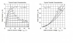
I looked at datasheet. Here's a picture. Sorry but English is not my native language. I do not know to which current limiting zener diode. I do not know what you're trying to say but does that mean that these output transistors do not need external current protection?
As i said before, Fischer SK47 150mm, around 0.56K/W.
Tc around 75degC max.
Attachments
yes,
look at where Vgs=7Volts goes.
Id starts very low when Vds is very low.
Id rises rapidly to ~5A as Vds goes towards 5Vds
Id then flattens off to just under 6A as Vds reaches 17Vds.
Looking at the slope of the Id vs Vds curves one can see that the maximum current that the FET can ever pass with Vgs=7V is <7A.
This means that if the Vgs is limited to 7V then the maximum current that can pass the FET is <7A.
There is your current limiting in event of a short circuit. = protection.
Now look at what happens if Vds is >17Vds and Vgs is limited to 7Vgs. The power dissipated is over 100W. The FET needs further protection in the medium term otherwise it will burn out. Fit supply rail fuses after the smoothing caps.
The Vgs can be limited with a Zener. But it also has a diode in series. The diode drops ~0.7V so a Zener ~6.3V will limit the maximum short circuit current to <7A
Now to temperature de-rated SOAR.
For Tc=25degC the Derating Factor (DF) is 1.
@ Tc=75degC the DF= [Tjmax - Tcoperating] / [Tjmax - 25degC] = [150-75]/[150-25] = 0.6
This tells us that the 100W FET must be de-rated to 60W and all the curves shown in the SOA must have the current reduced to 0.6*plotted current.
At 48V the FETs can pass 100W/48V * 0.6DF = 1.25A
A pair of parallel FETs can pass 2.5A when Vds=48V and Tc=75degC.
Similarly when driving a resistive load of 4r0 to 40Vpk, the Vds ~7V.
Now the FET can pass 100W/7V =14A. No, it is limited to 7Apk, a pair of FETs can pass 14*0.6 = 8.4Apk when Vds is <=14.3Vds (total dissipation is 120W split between two FETs).
Let's go back to
"At 48V the FETs can pass 100W/48V * 0.6DF = 1.25A."
This is a DC or continuous rating if one can keep Tc<=75degC (heatsink ~<65degC)
For a 100ms transient pulse (that happens once with time before the next single pulse to cool down) the pair of FET can pass 200W /48 * 0.6 * 2 = 5Apk That's the maximum current that a reactive load that lasts for 100ms can demand from the pair of FETs.
If the 10ms SOA is use then a fast 10ms transient can allow up to 7Apk demand into a very reactive load.
All this is in the datasheet, but it takes quite a bit of arithmetic to find all the limits that you might need.
That's why I adopted Bensen's SOAR spreadsheet.
Last edited:
!
Thanks for the explanation. Nice you wrote, if Vds> 17V DC and Vgs = 7V power dissipation is over 100W and transistor needs extra protection.Reading books, fuses negatively affect the performance of amplifiers and that fuses are not quick enough to react.Is it smarter to put overcurrent protection instead of fuses? In any case I have upc1237 or other protection, so I think not to put fuses but the overcurrent protection react to rescue transistors.
yes,
look at where Vgs=7Volts goes.
Id starts very low when Vds is very low.
Id rises rapidly to ~5A as Vds goes towards 5Vds
Id then flattens off to just under 6A as Vds reaches 17Vds.
Looking at the slope of the Id vs Vds curves one can see that the maximum current that the FET can ever pass with Vgs=7V is <7A.
This means that if the Vgs is limited to 7V then the maximum current that can pass the FET is <7A.
There is your current limiting in event of a short circuit. = protection.
Now look at what happens if Vds is >17Vds and Vgs is limited to 7Vgs. The power dissipated is over 100W. The FET needs further protection in the medium term otherwise it will burn out. Fit supply rail fuses after the smoothing caps.
The Vgs can be limited with a Zener. But it also has a diode in series. The diode drops ~0.7V so a Zener ~6.3V will limit the maximum short circuit current to <7A
Now to temperature de-rated SOAR.
For Tc=25degC the Derating Factor (DF) is 1.
@ Tc=75degC the DF= [Tjmax - Tcoperating] / [Tjmax - 25degC] = [150-75]/[150-25] = 0.6
This tells us that the 100W FET must be de-rated to 60W and all the curves shown in the SOA must have the current reduced to 0.6*plotted current.
At 48V the FETs can pass 100W/48V * 0.6DF = 1.25A
A pair of parallel FETs can pass 2.5A when Vds=48V and Tc=75degC.
Similarly when driving a resistive load of 4r0 to 40Vpk, the Vds ~7V.
Now the FET can pass 100W/7V =14A. No, it is limited to 7Apk, a pair of FETs can pass 14*0.6 = 8.4Apk when Vds is <=14.3Vds (total dissipation is 120W split between two FETs).
Let's go back to
"At 48V the FETs can pass 100W/48V * 0.6DF = 1.25A."
This is a DC or continuous rating if one can keep Tc<=75degC (heatsink ~<65degC)
For a 100ms transient pulse (that happens once with time before the next single pulse to cool down) the pair of FET can pass 200W /48 * 0.6 * 2 = 5Apk That's the maximum current that a reactive load that lasts for 100ms can demand from the pair of FETs.
If the 10ms SOA is use then a fast 10ms transient can allow up to 7Apk demand into a very reactive load.
All this is in the datasheet, but it takes quite a bit of arithmetic to find all the limits that you might need.
That's why I adopted Bensen's SOAR spreadsheet.
Thanks for the explanation. Nice you wrote, if Vds> 17V DC and Vgs = 7V power dissipation is over 100W and transistor needs extra protection.Reading books, fuses negatively affect the performance of amplifiers and that fuses are not quick enough to react.Is it smarter to put overcurrent protection instead of fuses? In any case I have upc1237 or other protection, so I think not to put fuses but the overcurrent protection react to rescue transistors.
I said Use the Zener as the current limiter. This is the short term protection.
eg. when the output is flashed with a short for a few ten's of milliseconds.
The Zener prevents extremely high currents passing through the FET if you select the Zener voltage appropriately.
The Output stage is protected from damage by the limited Vgs and little if any heat has been allowed to build upbecause this is a short term abuse situation.
The rail fuses are the medium term & long term overload protection. The fuse/s eventually blow to prevent the output stage and the heatsink overheating, if the short is kept on for a few hundred milliseconds or longer.
You must do both forms of protection that covers the range of short, medium and long term abuse.
The fuses I have referred to are in the supply rails. They have vitually no effect on amplifier output.
This is quite different from a speaker fuse between the amplifier and the speaker. Even when this fuse is brought inside the feedback loop (but few do this) it can effect the audio sound output when the amplifier and speaker are working normally, i.e. output fuses do not meet my criteria for protection: Protection systems must allow all valid Audio Signals to Pass to all valid speaker loads.
BTW,
do not quote the whole of another Member's post.
Extract the part you specifically want to comment further on.
Last edited:
- Status
- This old topic is closed. If you want to reopen this topic, contact a moderator using the "Report Post" button.
- Home
- Amplifiers
- Solid State
- Output protection