moamps said:Rth(BC639)=150K/W
Sorry, didn't understand. 150K/W ?
Kelvin per Watt, the measurement of thermal resistance. Exactly the same a C/W (Celcius per Watt). Multiply by power to get temperature rise. In your case, 0.6 * 150 = 90K above ambient temperature. With a maximum allowable junction temperature of 150C, ambient temperature must be less than 60C (assuming good airflow). It's pretty hot, but it will work.udip said:Sorry, didn't understand. 150K/W ?
Just break the feeback loop. 1mV may be too much if the open-loop gain is very high. You may need to add a DC bias to the input to keep the open-loop output centred on 0V.udip said:How do I measure open-loop gain (in simulations)?
should I just use a small signal for input (like 1mv), and use
no feedback? should I use a resistor from inv. input to ground?
Udi.
Mr Evil said:With a maximum allowable junction temperature of 150C, ambient temperature must be less than 60C (assuming good airflow). It's pretty hot, but it will work.
So I guess enclousing the whole thing in epoxy is out of
question...

thanh said:Hi! if i turn volume maximum, my speaker has "windy sound" .I thought that my amp wasn't stable! Now i have just found the reason . That sound's from pre-amp ,TL084 (but only use 1 of total 4 )
your pre-amp has balanced -input (do i mistake in my sentence? ) .A balanced-output,why not? perhaps if you do that, the mirror can be removed.
Hi,
I'm not sure I understand.
Please notice that it's a discrete opamp.
Udi.
udip said:Please notice that it's a discrete opamp.
Udi.
Nice circuit you've got!
I am sure it has great performance.
I dig them discrete operational amplifiers.
Hard to beat the fun to build them, when they work as you want.

Just break the feeback loop. 1mV may be too much if the open-loop gain is very high. You may need to add a DC bias to the input to keep the open-loop output centred on 0V.Originally posted by udip
How do I measure open-loop gain (in simulations)?
should I just use a small signal for input (like 1mv), and use
no feedback? should I use a resistor from inv. input to ground?
Udi.
Better yet, divide the output voltage by the voltage across the input LTP, V(out)/V(+in,-in). That way DC biasing is handled automaticly.
As for the compensation capacitor, one is better than two, the lefthand node (Q2 and Q9) of that current mirror will have nearly zero voltage swing on it so any compensation capacitor would merely load down the input LTP.
Hi,
the discrete opamp has a complementary push pull output stage.
The bias current (Iq) is only when no output signal is taken from the Re junction.
As you drive a voltage through the amp and feed current out to the load the current in one half of the output stage reduces and by design increases in the other half.
The maximum ClassA current is approximately double the Iq.
So, with Iq=17mA, max ClassA output ~=30mA.
Assuming a maximum output voltage about 2V below Vrail into minimum ClassA impedance, then it follows that 433r is the minimum impedance that allows the opamp to stay in ClassA.
To recap, with fixed two diode bias the Iq=17mA, Min Load impedance = 433r, max output voltage 13Vpk, 9.2Vac. and into 2k about 9.9Vac.
Remember that the feedback resistor is parallel to your load as far as current output is concerned.
EWorkshop1708 said:I like your fully mirrored design.
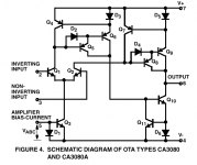
This discrete op-amp is very much alike CA3080 OTA ( Operational Transconductance Amplifier ).
Difference is that CA3080 uses no resistors
but instead uses more advanced current mirrors to achieve precision.
See attachment.
Attachments
lineup said:
This discrete op-amp is very much alike CA3080 OTA ( Operational Transconductance Amplifier ).
Difference is that CA3080 uses no resistors
but instead uses more advanced current mirrors to achieve precision.
See attachment.
I think it's more like OPA627.
Elso Kwak said:I think it's more like OPA627
Maybe in your imagination, Kwak
To me, it is clear it is not alike the JFET cascaded input Op-Amp you mention.
There are several other major differences.
But between CA3080 and this discrete. As I said, only a few resistors.
TOPOLOGY and IDEA
is the same.
lineup said:
Maybe in your imagination, Kwak
To me, it is clear it is not alike the JFET cascaded input Op-Amp you mention.
There are several other major differences.
But between CA3080 and this discrete. As I said, only a few resistors.
TOPOLOGY and IDEA
is the same.
Well let it put it this way : you have a FET differential stage followed by another differential stage with BJTs. This has been done by Hiraga many years ago, so what's new?
The OPA627 has an extra cascode stage in the input which I recommend for various reasons
Kaneda
Hi Jam,
Yes it IS a Kaneda.
jam said:Elso,
...............I think Kaneda used variations of that circuit years ago in fact it might be a Kaneda as his work was pretty popular in French diy circles.
Jam
Hi Jam,
Yes it IS a Kaneda.
Elso Kwak said:I think it's more like OPA627
anybody thinking ...
udip My discrete opamp
topology is more alike OP-Amp OPA627
than it is alike toplogy of OTA CA3080
... has spoken too soon
or does in fact not know the actual topology of CA3080
but it can be found, easily
I like the udip circuit.
It will perform extremely well in many applications
and needs we often run into.
For some apps, we can add a stage and make a slight modification
to make it suit perfectly.
But as a basic dicrete op-amp setup, it is in my opinion
very clever and good enough for most audio 20-50.000 Hertz
good work, udip!
thanks for publishing your circuit
Many Regards
lineup
- Status
- This old topic is closed. If you want to reopen this topic, contact a moderator using the "Report Post" button.
- Home
- Amplifiers
- Solid State
- My discrete opamp