I'll hope Jens will share his work with the Leach super amp with us all - at least on his own webside!
I'm no expert in eletronics, but - as the "skin dead book keeper" I am - I can follow a cooks recipe. The last 1½ year, I have learnt a lot in this forum, and I consult it every night.
I have build Jens' model of ESP's P3A - excelent sounding amp, but I was missing a bit of power. So what to do - called Jens and asked for his first leach amp version.
Sadly his was lost in a hardisc cash, so I build it with prof. Leach's board (made by myself). I have build 4 ordinary Low Tim amps and 2 super amps. All 6 with TO3's - Shure: I just hate wires!!! I had a problem with one of them, it run hot after a few minuts. What to do - I wrote to Jens. As the freindly person he is, he offered me at once his help. Before I got to Jens, I found the problem - where I live, we had a disaster i a firework factory, and the presior from the explosion had damaged my tweterband in my speakers (http://www.magnetostatic.com/). The tweterband was shorted, so the amp was working in something like 1 ohm or less. A new band in the speaker, and every thing was working - The Leach amp's sound wonderful!
Still - I want to build more, and I hate wires, so Jens pleace - Keep up the good working!
")
I'm no expert in eletronics, but - as the "skin dead book keeper" I am - I can follow a cooks recipe. The last 1½ year, I have learnt a lot in this forum, and I consult it every night.
I have build Jens' model of ESP's P3A - excelent sounding amp, but I was missing a bit of power. So what to do - called Jens and asked for his first leach amp version.
Sadly his was lost in a hardisc cash, so I build it with prof. Leach's board (made by myself). I have build 4 ordinary Low Tim amps and 2 super amps. All 6 with TO3's - Shure: I just hate wires!!! I had a problem with one of them, it run hot after a few minuts. What to do - I wrote to Jens. As the freindly person he is, he offered me at once his help. Before I got to Jens, I found the problem - where I live, we had a disaster i a firework factory, and the presior from the explosion had damaged my tweterband in my speakers (http://www.magnetostatic.com/). The tweterband was shorted, so the amp was working in something like 1 ohm or less. A new band in the speaker, and every thing was working - The Leach amp's sound wonderful!
Still - I want to build more, and I hate wires, so Jens pleace - Keep up the good working!
Hej Terry!
No I don't hear any diff. in the sound between the super amp and the Low Tim amp.
Neigher do I fell any diff. in the output, but the also sit on the same 40V-0-40V/500VA transformer with 60mF caps.
I have a plan of putting in an other transform of 20V-0-20V/500VA in serie with the first, and ad som 100V caps. In this way I can get (I think) about +-85 Volt for the super amp.
I have build the super amp, because my speakers have so low impedance - about 3 - 3½ ohm for the midrange and 2 - 2½ ohm for the high. Thats is also why I am so interested in Jens' 10 tansistor version.
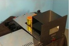
I will post some pictures, if I can borrow my wifes camera. I think it maybe shout be in the thread: "UGLY Looking Amp! - but good working", because the are made out of old computer stof, heatsink from old solarcells, free samples from ON semi and other old dead amps - Almost pure recycle!
Regards, Per
No I don't hear any diff. in the sound between the super amp and the Low Tim amp.
Neigher do I fell any diff. in the output, but the also sit on the same 40V-0-40V/500VA transformer with 60mF caps.
I have a plan of putting in an other transform of 20V-0-20V/500VA in serie with the first, and ad som 100V caps. In this way I can get (I think) about +-85 Volt for the super amp.
I have build the super amp, because my speakers have so low impedance - about 3 - 3½ ohm for the midrange and 2 - 2½ ohm for the high. Thats is also why I am so interested in Jens' 10 tansistor version.
I will post some pictures, if I can borrow my wifes camera. I think it maybe shout be in the thread: "UGLY Looking Amp! - but good working", because the are made out of old computer stof, heatsink from old solarcells, free samples from ON semi and other old dead amps - Almost pure recycle!
Regards, Per
Thanks Per,
I haven't heard the P3A but I just finished an ESP P101 using Rods boards and it sounds swell. If the Leach is better sounding I gotta get this thing done.
I'm not sure if I'll build another Superamp right away. I have two Hafler trannies that I beieve are 45-0-45V/450VA. I will probably look for something I can use one of those in for my next project. Very likely it will be Jens' Low TIM. I already have all or the transistors for it from On Semi.
I would like to try my hand at a class A amp however, so I may look for something in that design.
Blessings, Terry
Hello,
Now that acenovelty has got his own thread to promote his design work, maybe it’s time to pick up the work in this thread.
Hopefully we can now discuss flat pack type transistor layout without someone advocating to keep the TO-3 ones.
Everybody still interested, lets get it going again.
\Jens
Now that acenovelty has got his own thread to promote his design work, maybe it’s time to pick up the work in this thread.
Hopefully we can now discuss flat pack type transistor layout without someone advocating to keep the TO-3 ones.
Everybody still interested, lets get it going again.
\Jens
TO-3
Ahh no t-03 .Hee hee just kidding . I got 247's now SO I am in on new design.I am going to use all my to-3 for the regular leach.I do have a question capacitors though and I dont want to start one of those huge debate things like in every other search I did . I never did find any good answers.I see alot of the designs have those box type film caps in them . i ordered from Dr. leach parts list and the ones i got where not the box type.And on Jens board there are many box types.Is it okay to use Say silver mica for those caps or is it way over kill.with at least same voltage or higher.And does anyone have some good links to a thread that contains more then just people arguing over best types.And where do I find the wiki for Jens new design . I cant find it . Thank You all ,
Lee
Hello,
I have a question
What's your experience with mounting the board on top of the TO247 devices regarding heat transfer to the board material and adjacent components?
I can imagine it's getting hot above the output transistors, so - especially under the pressure of the mounting screws - could this harm the board/copper/components in the long run?
Sebastian.
JensRasmussen said:Everybody still interested, lets get it going again.
I have a question
What's your experience with mounting the board on top of the TO247 devices regarding heat transfer to the board material and adjacent components?
I can imagine it's getting hot above the output transistors, so - especially under the pressure of the mounting screws - could this harm the board/copper/components in the long run?
Sebastian.
Lee,
lets get it straight, you are by no means allowed to use other than square caps !
Even if they are better !
You are free to discuss anything about the SuperDuper as long as you agree with the ThreadMaster, otherwise you can always press the backbutton.
Oooooh, i've got these lovely Round Yellow Roe caps, you think i can use them ?
I've also got about a thousand small value styroflex caps, going to bypass every square/round capacitor with them.
Is the idea still to do a multiboard SuperLeach ?
http://members.aol.com/sbench102/caps.html
capacitor
I have some square ones too.I found some stuff on the web.I was just wondering How much sound dif can be with types.I know alot of people have done some testing and math.But what do the ears say . I got some extra low tim boards from dr leach , so I am gonna try dif stuff to see how it sounds later.I am going nuts stuck in hotel room without my bench and real tools . Only 2 months left.I also hate ebay now.I got three huge boxes of componets now.I got over 1000 silver mica caps now , 30000 resistors , a few thousand electrolitics, 500 or 600 transistors .I am gonna have to have a clearance sale before I go home hee hee.My poor garage , I am already out of space for stuff at home.Then I am going to have to get some real speakers to test with ,I only have some old mach III Optimus and small Infinity reference .
I have some square ones too.I found some stuff on the web.I was just wondering How much sound dif can be with types.I know alot of people have done some testing and math.But what do the ears say . I got some extra low tim boards from dr leach , so I am gonna try dif stuff to see how it sounds later.I am going nuts stuck in hotel room without my bench and real tools . Only 2 months left.I also hate ebay now.I got three huge boxes of componets now.I got over 1000 silver mica caps now , 30000 resistors , a few thousand electrolitics, 500 or 600 transistors .I am gonna have to have a clearance sale before I go home hee hee.My poor garage , I am already out of space for stuff at home.Then I am going to have to get some real speakers to test with ,I only have some old mach III Optimus and small Infinity reference .
You are sleeping on top of all those boxes of components, right ?
Why listen to what other people say, take any amplifier and bypass the powersupply capacitors by a foil type cap and see if you hear a difference.
imo, the entire tube section had a revival thanks to foil capacitors.
Why listen to what other people say, take any amplifier and bypass the powersupply capacitors by a foil type cap and see if you hear a difference.
imo, the entire tube section had a revival thanks to foil capacitors.
sek said:What's your experience with mounting the board on top of the TO247 devices regarding heat transfer to the board material and adjacent components?
imo, a lot of amplifiers have been built with boards directly attached to the heatsinks, both diy and commercial designs.
A number of those were class A amplifiers with TO3's.
With usually very little ventilation inside amplifier chassis, air and component temperature is likely to be close to the heatsink temperature anyway.
Not a bad thing, temperature variations influence the amplifier's behavior.
I have seen thermal pictures of a Threshold amplifier during warm-up. In the end state there was not a large temperature difference between different areas of the amp.
Downside is that electrolytic capacitors have the same temperature too, high temperature decreases capacitor lifespan considerably.
e.g. : www.duracap.com
Some took the step to place large capacitors on the exterior,
like yet another soundengineer gone amp designer, Costas Metaxas.
Attachments
Generally the heat will be transferred away from inside of the amps casing if you use the heatsinks as part of the chassis walls. I have measured the temperature inside the box of my prototypes and it’s about 35 degrees with an external ambient temperature of 22 degrees. If more cooling is desired I use a perforated top and bottom plate to cool the interior of the amp.
Components like the bridge rectifier and transformers get hot when the amp is used at higher levels. Therefore it’s a good idea to have perforated top and bottom plates in high power amps, along with heatsinks placed with the cooling fins outside the cabinet.
The temperature rise of the boards is small compared to the heatsinks. I placed the caps on the PCB away from the hot output transistors, and in a way that enables cooling by means of natural convection using perforated top and bottom plates.
I have seen some amps where the heatsinks are placed inside the enclosure. I don’t recommend this way of cooling, since the internal temperature of the cabinet will be much higher compared to the same amplifier with external heatsinks.
\Jens
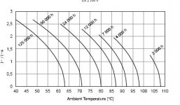
A general rule of thumb states that the life is doubled every time the temperature falls 10 degrees.
An example: 5.000 hours at 105 degrees. = 10.000 hours at 95 degrees = 20.000 hours at 85 degrees and so on.
That is pretty much what the life time multiplier graph that Jacco posted also shows.
It’s less of a problem in class AB amps. Class A is another matter because of heating from output stage and heating from the ripple currents in the caps.
\Jens
Which means that unless an amplifier like the Leach is used as a PA amplifier playing multiple Centurion the heatsinks are not that hot, and the pcb and components are hardly warm.
btw:
seems to me that Jens placed the board of the Extended Leach above the TO247.
It does not make a thermal contact to the devices, and there is plenty room between the board and the heatsink for ventilation.
I am also placing the board of the extended Leach at 0.4"- 0.5"above the heatsinks.
imo, placing output devices under the board, with holes for bolting them to the heatsink drilled in the pcb, is the optimal approach.
I've seen amplifier chassis with ventilation slits under and above the area between pcb and heatsink.
Thanks for your answers, and great to have the discussion back on topic.
In my original question about mounting the board on top of the output transistors I was actually more concerned about the board material itself.
As the mounting screws put a considerable force onto the FR4 and most laminates are only specified for temperatures little above 100 centidegree (full time) I was wondering about this method's durability.
After all, if the board material undergoes only a slight deformation (grow and shrinkage due to thermal cycling) the contact pressure could get reduced. And if the transistors aren't tightly fixed on the heatsink any longer...
But as Jacco stated, it's done "every day", so why bother too much? One could actually check and retighten the screws after a week or two of load test and listening, then it should actually have settled.
Whatever, it's certainly not a risk of fire or shock hazard...
Yep, I was also asking this out of interrest. The boards could be mounted to the transistor cases, so one can expect that a number of DIYers will certainly try it. Also, people like Rod Elliot or A. E. Holton even sell boards designed to be mounted that way...
Cheers,
Sebastian.
In my original question about mounting the board on top of the output transistors I was actually more concerned about the board material itself.
As the mounting screws put a considerable force onto the FR4 and most laminates are only specified for temperatures little above 100 centidegree (full time) I was wondering about this method's durability.
After all, if the board material undergoes only a slight deformation (grow and shrinkage due to thermal cycling) the contact pressure could get reduced. And if the transistors aren't tightly fixed on the heatsink any longer...
But as Jacco stated, it's done "every day", so why bother too much? One could actually check and retighten the screws after a week or two of load test and listening, then it should actually have settled.
Whatever, it's certainly not a risk of fire or shock hazard...
seems to me that Jens placed the board of the Extended Leach above the TO247
Yep, I was also asking this out of interrest. The boards could be mounted to the transistor cases, so one can expect that a number of DIYers will certainly try it. Also, people like Rod Elliot or A. E. Holton even sell boards designed to be mounted that way...
Cheers,
Sebastian.
- Status
- This old topic is closed. If you want to reopen this topic, contact a moderator using the "Report Post" button.
- Home
- Amplifiers
- Solid State
- Leach Super Amp Pcb Re-Design (LSAPRD)