I've been trying to think of ways to improve output stage linearity, and realized it would be a suitable task for the error correction discussed here recently.
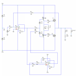
Applying the error correction only around the output stage, inside a normal negative feedback loop, avoids the poor clipping that it otherwise has (it tries too hard to pull the output above the physical limit). Because of the way that feedback is applied, the input impedance of the output stage is actually negative, but that isn't necessarily a problem. Benefits include improved linearity and reduced output impedance.
In the example attached, the input stage is an op-amp for simplicity. Distortion is low across the audio band, and because of the very low output impedance it remains virtually unchanged no matter what the load is (I've tested resistive loads down to 1 ohm, capacitive loads up to 10nF and modelled speakers).
Comments and suggestions welcome! I was wanting the output stage to have gain (by using Sziklai pairs with reduced feedback), but I haven't yet found an acceptable way of stopping cross-conduction.
Attachments
hello Mr Evil
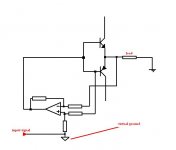
i made somthing simmilar to this a long time ago (see pic)
i dont know if i drawn it correctly (simplified), i got no time right now")
the idea is :
the op amp is a differential amplifier with a gain of one (all resistors are with the same value)
all that it does is simply taking the voltage falling on the Vbe of the output transistor and adds it to the input signal , that way input = output (in theory)
the difference between my circuit and yours is in my circuit the op amp got independant power supply with floating ground , so the input signal is connected to it , i think this makes the circuit much more complicated .
in the circuit i made i was using a good "tuned" instrumentation amp , rather then a differential ,and a compound output stage .
i made that circuit but didnt test it with any kind of distortion metter (because i aint got one), it was tested with music and it was ok , the output impedance was wirtually zero!!
i connected 0.1ohm resistor in parralell with the output and the music continued to play (the speaker was connected also) and the volume was unchanged!! (the output transistors got pretty hot)
i made somthing simmilar to this a long time ago (see pic)
i dont know if i drawn it correctly (simplified), i got no time right now
the idea is :
the op amp is a differential amplifier with a gain of one (all resistors are with the same value)
all that it does is simply taking the voltage falling on the Vbe of the output transistor and adds it to the input signal , that way input = output
(in theory)the difference between my circuit and yours is in my circuit the op amp got independant power supply with floating ground , so the input signal is connected to it , i think this makes the circuit much more complicated .
in the circuit i made i was using a good "tuned" instrumentation amp , rather then a differential ,and a compound output stage .
i made that circuit but didnt test it with any kind of distortion metter (because i aint got one
), it was tested with music and it was ok , the output impedance was wirtually zero!! i connected 0.1ohm resistor in parralell with the output and the music continued to play (the speaker was connected also) and the volume was unchanged!! (the output transistors got pretty hot
)Attachments
Simulations suggest that it can have good transient response as long as the error amp is appropriately fast. Measurements I did on the original (two op-amp) circuit showed this, so I expect it to hold true for this output stage too. I will build something like this eventually, but I feel that there is still a lot of improvement to be done first.anatech said:It would be interesting to see what happens at high freqencies and with impulses. Build it and feed it a differentiated square wave.
'Scope input and output to see phase and amplitude relationships.
-Chris
Yes, it must be very fast. As discussed in the origianl thread I linked to, the error amp must be faster than the main amp (the output stage in this case). I'm still looking for a suitably fast op-amp with wide phase margin. The simulations are done with NE5534, which works well but could be faster. I considered making a discrete differential amp using RF transistors for this, but the gain would be low, negating most of the advantages of the configuration.sajti said:I think that the error corrector opamp must be the fastest You can get. If no, there will be problem with the delay of the error correction, and it will results more distortion. Very strange distortion....
sajti
Yeah, that's very similar except that in your case the op-amp is also in the signal path, whereas in my case it only amplifies the error. Good to hear it worked, so I know I'm on the right tracksss said:hello Mr Evil
i made somthing simmilar to this a long time ago (see pic)...
I think this is possibly the biggest advantage of this sort of design. I know some people complain that amps are not designed with the complex load of a loudspeaker in mind, but if the amp is totally insensitive to load impedance then it doesn't matter what load you design it to work with, it will still work exactly the same with any other load.sss said:...i connected 0.1ohm resistor in parralell with the output and the music continued to play (the speaker was connected also) and the volume was unchanged!! (the output transistors got pretty hot
I don't have a distortin meter either, so what I did was deliberately increase distortion by adding diodes in the signal path. Then the distortion is clearly visible on a scope and it's possible to make a rough measurement of the amount of improvement. That isn't suitable for measuring all methods of reducing distortion, but it's useful here.
Mr Evil said:I don't have a distortin meter either, so what I did was deliberately increase distortion by adding diodes in the signal path. Then the distortion is clearly visible on a scope and it's possible to make a rough measurement of the amount of improvement. That isn't suitable for measuring all methods of reducing distortion, but it's useful here.
The most interesting is the signal on the output of the error correction amplifier.
So, it will work with NE5534, but You have to use low pass filter on the input, to reduce the bandwidht to about 80-100kHz. In this case, there will be no very fast signal at the output stage..
sajti

lumanauw said:I found this cct, what is it doing? Is it Error Correction or Non-Turnoff scheme or what? The biasing part is strange.
Hi
For me, it just look like the protection circuit for the lower half of the amp...
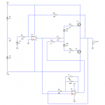
I've attached an improved version. Initially I had buffered the FETs because I wanted a low input capacitance, but I realized that this is unnecessary because the error amp forces the input impedance to be resistive. Losing the BJTs makes it possible to limit the bandwidth by altering the size of R1, which forms a low-pass with the FET's input capacitance. This makes it easier to stabilize the circuit.
The second change is lowering the ratio of direct input to error-correction by making R1 > R4. This reduces the voltage swing required from the error amp so it doesn't clip too early, and increases the magnitude of the input impedance (more negative, that is).
Lastly I found a suitable op-amp for the error-amp. AD817 has a gain-bandwidth product of 50MHz and a wide phase margin which makes for a much greater stability overall, allowing a larger amount of error correction. 50mA output current also helps charge/discharge the MOSFETs quickly. I've not seen it used for audio before, but on paper it is superb. Input op-amp is a plain old OPA604, but anything that isn't too fast will do there.
The circuit is now really rather simple and simulations suggest it would have one of the lowest distortions of any amp I've made, as well as good bandwidth, damping factor as close to infinity as you like and good transient response.
That's ideal for getting the last drop of performance out of a circuit, but op-amps are too convenient: Just three or four components instead of a dozen or more, and good ones give excellent performance in almost all aspects compared to discrete amps.lumanauw said:How about making your idea with discrete components (without opamps)?..
It could be a non-turn-off circuit. It certainly doesn't reverse bias the output devices.lumanauw said:...I found this cct, what is it doing? Is it Error Correction or Non-Turnoff scheme or what? The biasing part is strange.
Attachments
The gain doesn't have to be that high. If the gain was one, then there would still be a few dB of error correction. Lower gain makes stability easier to accomplish, but since the output stage has only unity gain this is much easier anyway, so I can get away with high gain for the error amp.
Mr Evil said:The gain doesn't have to be that high. If the gain was one, then there would still be a few dB of error correction. Lower gain makes stability easier to accomplish, but since the output stage has only unity gain this is much easier anyway, so I can get away with high gain for the error amp.
If the error amp gain was exactly unity, you would have 100% error correction. This is the original work of Hawksford. By increasing the error amp gain, you have no longer a Hawksford error correction but a normal negative feedback loop around the output stage. In that case, you no longer have exact cancellation (unless in the limiting case that the error amp gain is infinite).
(Of course all regular feedback is also a form of error correction, but I assume you mean the Hawksford error correction.)
Jan Didden
No, it's slightly different here. Hawksford's error correction is feedforward, so subtracting exactly the error from the output results in the output being exactly equal to the input. In this case it is feedback, so subtracting exactly the error from the input causes the amplifier to be amplifying (input - error), but it will now distort this new input. More error gain removes this new error too, but causes new, even smaller errors.janneman said:If the error amp gain was exactly unity, you would have 100% error correction. This is the original work of Hawksford. By increasing the error amp gain, you have no longer a Hawksford error correction but a normal negative feedback loop around the output stage. In that case, you no longer have exact cancellation (unless in the limiting case that the error amp gain is infinite).
(Of course all regular feedback is also a form of error correction, but I assume you mean the Hawksford error correction.)
Jan Didden
I know feedback is error correction, I just called this EC hoping to make it clear what I was talking about!
Mr Evil said:No, it's slightly different here. Hawksford's error correction is feedforward, so subtracting exactly the error from the output results in the output being exactly equal to the input. [snip]
Hawksford error correction is not subtractive, it get the "missing" part from the output and adds that to the input (1:1). So, if you have unity gain, the correction is exact.
Mr Evil said:[snip] In this case it is feedback, so subtracting exactly the error from the input causes the amplifier to be amplifying (input - error), but it will now distort this new input. More error gain removes this new error too, but causes new, even smaller errors.
I know feedback is error correction, I just called this EC hoping to make it clear what I was talking about!
Yes you clearly describe feedback as we all know it. I really don't see why you would call feedback "error correction" to make it more clear and in the process mixing it up with error correction as developed by Hawksford. Why not calling feedback "feedback"?? I know it's not very sexy and all that, but it IS clear...
Jan Didden
Sorry, if I've misunderstood Hawksford's approach then it is actually the same in principle to what I have here. It's not the same as normal NFB where the output is subtracted from the input, here only the error (output - input) is subtracted from the input. But still, unity gain is not enough - that will only give ~6dB of improvement, which is easily verifiable by experiment or simulation.janneman said:
Hawksford error correction is not subtractive, it get the "missing" part from the output and adds that to the input (1:1). So, if you have unity gain, the correction is exact.
Yes you clearly describe feedback as we all know it. I really don't see why you would call feedback "error correction" to make it more clear and in the process mixing it up with error correction as developed by Hawksford. Why not calling feedback "feedback"?? I know it's not very sexy and all that, but it IS clear...
Jan Didden
Mr Evil said:
Sorry, if I've misunderstood Hawksford's approach then it is actually the same in principle to what I have here. It's not the same as normal NFB where the output is subtracted from the input, here only the error (output - input) is subtracted from the input. But still, unity gain is not enough - that will only give ~6dB of improvement, which is easily verifiable by experiment or simulation.
Well, if you calculate OR measure the Hawksford method, you will see that unity gain gives EXACT error cancellation - that's the whole idea! The (counter-intuitive) thing is that if you increase the correction gain above unity, the error re-appears!
see http://www.essex.ac.uk/ese/research/audio_lab/malcolms_publications.html pubs J3 (&J4, but J3 is the basic paper).
Jan Didden
- Status
- This old topic is closed. If you want to reopen this topic, contact a moderator using the "Report Post" button.
- Home
- Amplifiers
- Solid State
- Another error correction output stage.