I think it would work, but remember that you have 4 extra transistors in the signal path and each of them introduces an additional pole in the open loop transfer function... ie : more compensation required for stability
If you like the advantages of operating the input stage and the VAS with +-15V supplies I strongly recommend an output stage with floating power supplies
As an example, this is how QSC does it in most of their amplifiers. Note that grounding collectors makes any insulation between output devices and heatsinks unnecesary
Attachments
Great point Eva, about the compensation needed, makes it sort of pointless to be serious about. Suppose it might make a good oscillator. 
Interesting that the audio goes through the voltage source. It looks like you would need two power sources for that circuit because if the low voltage was regulated from the high, there would be no reference for 0V for the low.
Interesting that the audio goes through the voltage source. It looks like you would need two power sources for that circuit because if the low voltage was regulated from the high, there would be no reference for 0V for the low.
There are many circuits similar to this using an op-amp as the input stage. It's possible to make them stable by applying heavy frequency compensation around the input stage, i.e. turning it into an integrator, and keeping the gain of the output stage reasonable.
The point of such circuits is usually to get a high-voltage output from an op-amp. I don't see any particular reason to make a discrete version.
The point of such circuits is usually to get a high-voltage output from an op-amp. I don't see any particular reason to make a discrete version.
The QSC circuit works as it is, it doesn't require regulated supplies, it only requires good layout. Note that the output stage works as two controlled current sources
Having a front-end powered witn +-15V supplies has a lot of advantages, it allows to use low-noise high-beta high-bandwidth low-voltage transistors, even JFETs, and it does not require any cascoding for high power output, so component count is much smaller
PSRR is dramatically improved since the +-15V supplies are now regulated and current sources may be achieved with simple resistors. Furthermore, the VAS is no longer a VAS since it operates at constant Vce so there is no VAS distortion due to miller effect
Overall, the component count in the signal path is reduced and the bandwidth is improved. It only requires separate power supplies for each channel, and a lot of people are already using them
Note that I'm considering the discrete version, not the op-amp based version that features not so good performance but extreme simplicity
Eva said:The QSC circuit works as it is, it doesn't require regulated supplies, it only requires good layout. Note that the output stage works as two controlled current sources
Having a front-end powered witn +-15V supplies has a lot of advantages, it allows to use low-noise high-beta high-bandwidth low-voltage transistors, even JFETs, and it does not require any cascoding for high power output, so component count is much smaller
PSRR is dramatically improved since the +-15V supplies are now regulated and current sources may be achieved with simple resistors. Furthermore, the VAS is no longer a VAS since it operates at constant Vce so there is no VAS distortion due to miller effect
Overall, the component count in the signal path is reduced and the bandwidth is improved. It only requires separate power supplies for each channel, and a lot of people are already using them
Note that I'm considering the discrete version, not the op-amp based version that features not so good performance but extreme simplicity
Hi Eva,
are the comments regarding the schematic you posted in
post #2
I am suspicous with the floating powersupply of +-50 VDC, the powersupply must be very carefully designed, not espsecially to differential mode disturbans from the mains, but to common mode disturbans
And the earthing is also very critical, both signal and mains earthing!
Further the output signal is loaded depending on the PSU impedance in the whole audio frequency range, and feedback will be sensitive too to disturbances.
Irrespective of the frontend voltage there is up to 100 volt Vce.
I don't agree thereby that the VAS (if are talking about does 2 transistors drived by the opamp) don't see any varrying Vce voltage, the floating voltage is jumping up and down up to +-50 Volts with the audio signal.
Well, the bandwith is gone since the voltage is changing a lot over the VAS.
All in all the circuits easy looks realy cheats the eyes!
Regards Michael
Ultima Thule said:
Hi Eva,
are the comments regarding the schematic you posted in
post #2
I am suspicous with the floating powersupply of +-50 VDC, the powersupply must be very carefully designed, not espsecially to differential mode disturbans from the mains, but to common mode disturbans
And the earthing is also very critical, both signal and mains earthing!
Further the output signal is loaded depending on the PSU impedance in the whole audio frequency range, and feedback will be sensitive too to disturbances.
Irrespective of the frontend voltage there is up to 100 volt Vce.
I don't agree thereby that the VAS (if are talking about does 2 transistors drived by the opamp) don't see any varrying Vce voltage, the floating voltage is jumping up and down up to +-50 Volts with the audio signal.
Well, the bandwith is gone since the voltage is changing a lot over the VAS.
All in all the circuits easy looks realy cheats the eyes!
Regards Michael
I think the circuit is actually cheating at your eyes. Everything you mentioned already happens in any standard class B or AB amplifier
The drivers and the output devices allways suffer from miller effect and the power supply is allways part of the open-loop transfer function of the amplifier
And common mode filters are also required in standard topologies to prevent RF currents to flow between signal ground and mains line, but nobody uses them anyway
I've experimented with this topology using discrete front-end and EF output, and the only drawback I've found is that it requires separate power supplies and good layout
Obviously you haven't still tried it, so I suggest you to experiment with it first
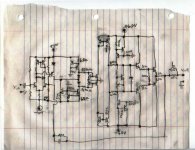
My test circuit looked like that :
An externally hosted image should be here but it was not working when we last tested it.
An externally hosted image should be here but it was not working when we last tested it.
But I used only one pair of drivers and two pairs of output devices due to lack of money. The bread-board prototype worked fine driving 4 ohms with +-85V rails [experimentation is currently interrupted also due to a chronic lack of money]
I experimented >30Mhz local oscillations on the output stage until I got a proper layout, and 2.5Mhz global oscillations until I found proper compensation [dominant pole plus pole-zero for 9dB/oct rolloff], this helps to figure out the bandwidth of such a circuit
At the end we get something like a 1000W@4ohm circuit with the performance of a 100W@4ohm one
Only if the required output current is larger than the bias current. With high enough bias current they are class A.darkfenriz said:hi cunningham
I would like to mention that your current mirrors between 'low voltage' and 'high voltage' sections seem to work in class B, don't they?
darkfenriz said:hi cunningham
I would like to mention that your current mirrors between 'low voltage' and 'high voltage' sections seem to work in class B, don't they?
I was thinking that since the two diodes are always forward biased, there would be 0.6V accross the source transistors keeping them just above cuttoff for 0V signal. This keeping thier mirrors just above cuttoff and so-on. Usually the forward V drop of the diode is slightly more than the Vbe turn-on. This circuit might be good to drive a sub-woofer, in that less compensation would be needed for lower frequencies. I'm not really sure it would work at all, I've never tested it or simulated. I just thought up the topology the other day. Wonder if that circuit (from post 1) would make a good bi-directional motor drive circuit.
- Status
- This old topic is closed. If you want to reopen this topic, contact a moderator using the "Report Post" button.
- Home
- Amplifiers
- Solid State
- Would this circuit work???