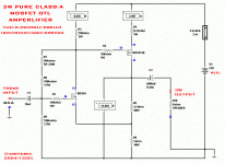
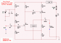
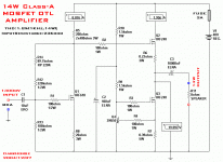
Darkhorse, this is one I made about 2- 1/2 years ago and is still going well. It uses a big choke instead of a resistor and so it has half the power loss than usual.
Circuit. http://www.diyaudio.com/forums/attachment.php?s=&postid=183394&stamp=1054194645
The complete thread.
http://www.diyaudio.com/forums/showthread.php?s=&threadid=6338&perpage=50&highlight=&pagenumber=1
Circuit. http://www.diyaudio.com/forums/attachment.php?s=&postid=183394&stamp=1054194645
The complete thread.
http://www.diyaudio.com/forums/showthread.php?s=&threadid=6338&perpage=50&highlight=&pagenumber=1
PMA said:Nice design. Please let us know your listening impressions. Maybe you are losing a little bit more power than necessary

hi,PMA:
the amp didn't work out yet!But trying my best now--buying electric device and its out shell ..etc
I hope the circuit will sounds good,my friend told me that can it compare with 2A3 vacuum tube amp..
in fact,I don't own both of them now..haha
same as you expect,I doing things for it!
have fun!
Circlotron said:Darkhorse, this is one I made about 2- 1/2 years ago and is still going well. It uses a big choke instead of a resistor and so it has half the power loss than usual.
Circuit. http://www.diyaudio.com/forums/attachment.php?s=&postid=183394&stamp=1054194645
The complete thread.
http://www.diyaudio.com/forums/showthread.php?s=&threadid=6338&perpage=50&highlight=&pagenumber=1
hello,Circlotron:
I read your post thread "My first ever Class A amp",we almost have same idea of class-a amp form,yours is using inductance winding,the efficiency near to 50%...High!I saw the same idea in passlab.com, nelson pass new design zen-7,good idea..
but the high quality inductance is hard to DIY or buying!is it?
I don't want to change my mind-Use aluminium case power resistance,only this I can choose for this circuit..
and I hope it will sounds truly..
happy!
Hi Darkhorse,
Please don't think that I am picking on you personally, but I so often see 'simple' circuits like these.
Yes (Post 10) will work, and it has simple internal ac and dc feedback, but ......... nobody ever seems to comment on the fact that the control of loudspeaker back emf is asymmetrical, and thus the amplifier's output is liable to become characterised by the crossover/loudspeaker combination much more than is the case with an output stage that is capable of *actively* conducting both positively and negatively.
For example there can be a hefty NFB controlled positive current flow via M1, but only the current due to (1 + 6.8 + speaker) ohms flowing negatively.
Cheers ........... Graham.
Graham Maynard said:Hi Darkhorse,
Please don't think that I am picking on you personally, but I so often see 'simple' circuits like these.
Yes (Post 10) will work, and it has simple internal ac and dc feedback, but ......... nobody ever seems to comment on the fact that the control of loudspeaker back emf is asymmetrical, and thus the amplifier's output is liable to become characterised by the crossover/loudspeaker combination much more than is the case with an output stage that is capable of *actively* conducting both positively and negatively.
For example there can be a hefty NFB controlled positive current flow via M1, but only the current due to (1 + 6.8 + speaker) ohms flowing negatively.
Cheers ........... Graham.
hi,Graham Maynard :
that is realy matter what your said,I will be back tomorrow,
..sorry!haha..time to off duty now..
happy!
PMA said:The circuit shown may serve as a "starting point" of the newbie el. designer. After he sees all the design flaws and problems he may move to higher circuit league - in this case the attempt would be valuable.
hello,PMA:
haha...your word is funny and exactly,I don't feel any unsuitable
in this schematic,but I know if the amp runs,it's result will make me know more about the true!I will kept trying..
regards,
WINCO

perhaps,this circuit form is more fit to be preamp or headphone amp..
it's too low efficiency,when as a power amplifier..
and it hard to using constant current source instead of resistor..
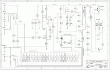
here is the schmatic (author is our master:Nelson Pass) which I got it from internet,the main circuit form same as mine,but it is a preamp circuit:
it's too low efficiency,when as a power amplifier..
and it hard to using constant current source instead of resistor..
here is the schmatic (author is our master:Nelson Pass) which I got it from internet,the main circuit form same as mine,but it is a preamp circuit:
Attachments
hello,Upupa Epops ,PMA:Upupa Epops said:If you can easy to build amp, try PMA's " Mosfet follower ". Many positive references on this forum. Efficiency of this connection is more better.
I have checked "MOSFET FOLLOWER",but find nothing..Wowo..
can you do me a favour to show this thead where?
best regards,
WINCO
Look at www.pha.inecnet.cz/macura/audiopage.html - Mosfet Power Follower.
Upupa Epops said:Look at www.pha.inecnet.cz/macura/audiopage.html - Mosfet Power Follower.
wah..PMA is an great designer!I fell so surprise when visit the link
which is offered by Mr.Upupa Epops,thank you two!
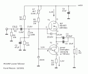
here is PMA's "mosfet power follower":
Attachments
here I have draw a circuit same as PMA's,but it's not easy to
regulating the out point voltage to 1/2Ucc,maybe need a high power resistor to help..perhaps,I will build it next..
and I will not give up with"3W Pure Class-A AMP",very eager to
do something for it (lastest version is 4W)now..

regulating the out point voltage to 1/2Ucc,maybe need a high power resistor to help..perhaps,I will build it next..
and I will not give up with"3W Pure Class-A AMP",very eager to
do something for it (lastest version is 4W)now..

Attachments
- Status
- This old topic is closed. If you want to reopen this topic, contact a moderator using the "Report Post" button.
- Home
- Amplifiers
- Solid State
- 3W Pure Class-A AMP
