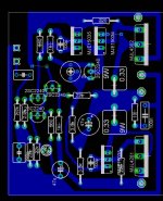
It looks like you would be able to get around 1 of those top side jumpers if you routed pin 2 of the MJE15034 around the other side of pin 3. You'd cut into your VCC plane only a little bit in doing so.
There look to be quite a few ways of routing around the other top side jumper as well but those are less straight forward.
Other than that, build it and let us know how it comes out.
--
Danny
There look to be quite a few ways of routing around the other top side jumper as well but those are less straight forward.
Other than that, build it and let us know how it comes out.
--
Danny
Hi, i borrow your thread a little, hope its ok.
Im totally new in all this amp-building. Ive got a idea that i should build an amp and found the Project 3A wich sound like a good beginner project. Ive got some basic electronic knowlage and soldiering is not a prob for me. Now i got all the electronic components i need fpr the amp. I feel like i do NOT have the knowlage to do, is to design the PCB myself. Now i wonder where to find a good PCB to use. This one looks good, but i have no experience in this so my oppinion is worth nothng.
I do not care that much about how super good it sounds, as long as it aint sound like crap. This projekt is for me mostly the fun in building and creating. Not to get the best sound in the world if you understand what i mean.
If you would like to send me your .pcb file it would be great! my e-mail is tamazerd@hotmail.com
New Update
An externally hosted image should be here but it was not working when we last tested it.
Attachments
Tamaz>>
You could find some quite easy circuit to start with. If its not too advanced you can build it on "löd-torn" Its like a lenght of metall pieces you can solder on. It gets very provisoriskt and not so good looking but it works. Should be avialable at an electronic stuff store or something like that. Its probarly easier and cheaper then making a pcb.
I built a chip amplifier on this stuff and it worked very well. Might be tighter to build with discrete components but its quite fun to array and fix it in your own way.
Pic of the amp
http://upl.silentwhisper.net/uplfolders/upload5/P7280004.jpg
This is the first of my amp projects that actually worked Im intending to build a discrete solid pass amp further on though
link to the project
http://www.electro-dan.co.uk/electronics/TDA2040.html
Its an easy project and cheap. 20W integrated circuit for about 50SEK
Sorry for disturbing the thread
You could find some quite easy circuit to start with. If its not too advanced you can build it on "löd-torn"
Its like a lenght of metall pieces you can solder on. It gets very provisoriskt and not so good looking but it works. Should be avialable at an electronic stuff store or something like that. Its probarly easier and cheaper then making a pcb. I built a chip amplifier on this stuff and it worked very well. Might be tighter to build with discrete components but its quite fun to array and fix it in your own way.
Pic of the amp
http://upl.silentwhisper.net/uplfolders/upload5/P7280004.jpg
This is the first of my amp projects that actually worked
Im intending to build a discrete solid pass amp further on thoughlink to the project
http://www.electro-dan.co.uk/electronics/TDA2040.html
Its an easy project and cheap. 20W integrated circuit for about 50SEK
Sorry for disturbing the thread
Hy roly3055! Can you send me the PCB and the schematic for this amp.
My mail is beatDj05@yahoo.com
Thanks a lot.
My mail is beatDj05@yahoo.com
Thanks a lot.
That's an enormous input capacitor
Douglas Self claims that it is important that the negative feedback takeoff point is taken exactly between the power-resistors a small bit in on the output track, and not a little bit closer one of the resistors so it gets the exakt output voltage.
else it looks nice
Douglas Self claims that it is important that the negative feedback takeoff point is taken exactly between the power-resistors a small bit in on the output track, and not a little bit closer one of the resistors so it gets the exakt output voltage.
else it looks nice
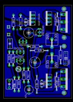
chicco_36 said:Hi r!sc!,
What type of output transistors you use on your pcb? Pinout is strange or I’m missing something?
Pozdrav sa juga!
Hi there,
I use ON MJL21193/94 trans. Drivers are ON MJE15032/33.
Kako je u makedoniji? Pozdrav!
chicco_36 said:If I remember correctly of MJL output transistors pinout, and since your picture is mirrored, you have nice and healthy +-35V on your bases! Did you actually build this amp?
I hope I'm wrong!
I see nothing wrong with the layout. r!sk!'s artwork shows the traces on the bottom of the PCB as seen from the component side, as if the PCB material were invisible. Printing this as is works well when using the toner transfer method to etch PCBs.
- Status
- This old topic is closed. If you want to reopen this topic, contact a moderator using the "Report Post" button.
- Home
- Amplifiers
- Solid State
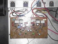
- Please comment my pcb P3a