Hi all,
I have not been back in this thread for a while, even I started it. The reason is that I fixed both amps, gave one to a friend and sold another. So I no longer have any. There were decent amplifiers, but I do have very efficient speakers and the background noise and crossover distortion al low level was audible.
I might still have original service manual, I can scan it and send out high resolution pdf if anyone interested.
I will get back on that.
ed
hi.
Refering to this schematic:
http://www.diyaudio.com/forums/attachment.php?s=&postid=554005&stamp=1105975431
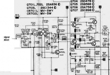
A tweaking idea that would maybe give higher 'hif-fi' sound, would be
Remove/Disable Loudness + Bass + Treble + Low-filter.
And so pass signal directly to resistor R616L
Many hi-fi amplifiers have Tone-defeat and Direct switches, for best audio.
See my attachment.
Refering to this schematic:
http://www.diyaudio.com/forums/attachment.php?s=&postid=554005&stamp=1105975431
A tweaking idea that would maybe give higher 'hif-fi' sound, would be
Remove/Disable Loudness + Bass + Treble + Low-filter.
And so pass signal directly to resistor R616L
Many hi-fi amplifiers have Tone-defeat and Direct switches, for best audio.
See my attachment.
Attachments
Thanks jcone for the transformer voltage. I may rewind as finding a match could be trickier.
Adason, if you have and litterature on it, I'd much appreciate a copy. I would like to get this amp back up and running and perhaps change out a few components depending how it sounds.
Adason, if you have and litterature on it, I'd much appreciate a copy. I would like to get this amp back up and running and perhaps change out a few components depending how it sounds.
Hi, I have one of these amps on my test bench at the moment and while it runs ok, and doesn't have any noticeable noise, the output transistors are getting quite hot - even when it is sitting there idling with no input and the volume set to zero.
Suspecting that the bias may be too high, I measured the DC on the outputs - between 140 - 180 mV.
Left and right channels are about the same so nothing obvious there.
Voltages on the base and emitter of the output transistors look Ok as well.
Any bright ideas as to why they are getting so hot? They're not so hot as to be untouchable, but more the heat one would expect from an amp that is running at 3/4 volume.
I first noticed it when it had been sitting running for half an hour and I could smell "heat" - so I took a closer look and realised the top of the amp was quite warm.
Adason, could you email me the PDF full version manual please? My email address in my profile should be able to handle it.
Crap. I just had the most wonderful post in the making and then I thought of embedding a link by clicking that nice http:// button and hadn't allowed javascript. That lost my nice message.
Adason, could you send me a copy of the manual.
I saw that there's been a review in the November 1978 issue of Stereo Review. Anyone happen to have that and willing to give a short summary of what it says?
Adason, could you send me a copy of the manual.
I saw that there's been a review in the November 1978 issue of Stereo Review. Anyone happen to have that and willing to give a short summary of what it says?
Progress on my modification
So I have completed phase one of my modifications.
This was an excercise in looking at the two gifs+jpg posted earlier. Now comes the fun part when I work towards the second of the gifs and it's darn close to unreadable. Still waiting for adason to be kind enough to send me a pdf. New member, so can't send emails yet. In case anyone else has the pdf, please send it to me.
The following is an excerpt from a diary of sorts I'm writing for this modification.
---
Problem: Really didn't like the way power was coming in to the amp. 10" long connector on the outside and routing of power inside together with secondaries and speaker cables.
Solution: Added IEC C14 chassis socket for power. Currently screwed to hole left by removal of speaker B plate. Incoming power routed on back, left of transformator using two conductor 1.5mm2 cable. Socket should really be C18 as connecting power ground to chassis (=secondary, signal, and speaker ground) has a very bad effect on sound. Or I could investigate this more.
---
Problem: Not a real problem, but as everything is on an experimentation stage, the transformer/chassis is some 2' away from the PCB. Need some convenient way of connecting/disconnecting the two.
Solution:
Cables from transformer changed to black for ground and red+yellow for others. Screw connector (don't remember/know the correct english term) added. Should probably change the connector to something allowing for faster and more reliable connect/disconnect. Maybe a computer connector.
---
Problem: Volume control is bad, loudness didn't seem to do anything, signal routing is ugly.
Solution:
Currently connecting directly to R616x bypassing balance, loudness, volume, and the bass/treble sections. The way I did this was by desoldering and lifting the legs of R620x, R613x, and C612x. Connection is by a piece of RCA cable (non-teflon cable that tends to melt real easy) soldered directly to the legs of R616x. Makes it real nice to route the signal cable on the front and right side far away from nasty noise sources.
---
Problem: Speaker cables were cut at some point and had to be replaced.
Solution: Connecting 0.75mm2 Speaker cables to 16 and 17.
---
Problem: J1 and J2 routed on component side of board. Didn't like it.
Solution: Re-route to solder side.
---
Current status after modifications:
Signal input is 3.5mm connector by long cable directly soldered to R616x.
Speaker output is DIN 41529 loudspeaker connector by 1.5' 0.75mm2 speaker cable directly
soldered to 16, 17 and to ground.
Headphone (14 and 15) disconnected from PCB.
Power level meter disconnected from PCB.
RIAA amplifier saved for possible future use. Throw and rotary switches desoldered.
Volume and balance control board scrapped.
A lot of the bad noise is gone and left is some sweet, soothing white noise audible when putting my ear real close to a MDS Fanatic 5.25" 2-way speaker (4 ohm, 91.6dB/W).
---
Future work:
Continue working through the signal path towards speakers.
Think about how/what to do with balance/volume control and tape/input selectors.
gilleSO: Sorry to reply so late. I have been quite busy with work and life. Are you still looking for the manual, in that case just reply with yes and I can mail it to you ")
Others: I am still having problems to source (mostly my problem as I haven't ordered any electronics related parts in a while). Currently I have bypassed a lot of the input capacitors and am in the process of resoldering the transistors. I'm currently waiting for AlOxide insulators for the transistors. The only part I haven't decided is the insulators for the "legs". As soon as I do that I will have a working amplifier. For the moment it will be with no volume control, so I need a pre-amp which was a potentiometer that was totally unshielded. But still it got me some real nice sound, but it was some distance from the computer (i.e. my source).
I am cery happy with the sound quality of this amplifier and would like your input on my ideas of using AlOx as insulator. I think it should work very well, but I should put a thin layer of something like arctic silver on the contact surfaces, right?
Others: I may still put a volume (and other) control as these fit in the chassis, but the existing volume control was oxidized beyond repair for some reason. Any suggestions for a fitting volume control? I may consider playing around with something like the light speed attenuator, but I think it might be as well to put the attenuators outside the chassis (i.e. attenuator, balance, etc...), right?
peteran said:gilleSO: Sorry to reply so late. I have been quite busy with work and life. Are you still looking for the manual, in that case just reply with yes and I can mail it to you
Others: I am still having problems to source (mostly my problem as I haven't ordered any electronics related parts in a while). Currently I have bypassed a lot of the input capacitors and am in the process of resoldering the transistors. I'm currently waiting for AlOxide insulators for the transistors. The only part I haven't decided is the insulators for the "legs". As soon as I do that I will have a working amplifier. For the moment it will be with no volume control, so I need a pre-amp which was a potentiometer that was totally unshielded. But still it got me some real nice sound, but it was some distance from the computer (i.e. my source).
I am cery happy with the sound quality of this amplifier and would like your input on my ideas of using AlOx as insulator. I think it should work very well, but I should put a thin layer of something like arctic silver on the contact surfaces, right?
Others: I may still put a volume (and other) control as these fit in the chassis, but the existing volume control was oxidized beyond repair for some reason. Any suggestions for a fitting volume control? I may consider playing around with something like the light speed attenuator, but I think it might be as well to put the attenuators outside the chassis (i.e. attenuator, balance, etc...), right?
Sorry to reply so late. I have been quite busy with work and life. Are you still looking for the manual, in that case just reply with yes and I can mail it to you
there is got to be some missunderstanding here !!!!! the way you write things looks like you mean that sound, amps, and electronics is not part of life .....
there is about 100.000 forum members that will be willing to proove you wrong

best regards sakis !!!!
please...
Please help...I need a service manual for HITACHI HA 330!
Please post on ejder_ates@hotmail.com
Thanks
Please help...I need a service manual for HITACHI HA 330!
Please post on ejder_ates@hotmail.com
Thanks
still need a service manual
Sorry friends...
I forgot my username & passwprd and I can`t sign in in this forum until now!
Please forgive me!
I still need a service manual or shematic for HITACHI HA 330!
Send me to dradnic972@yahoo.com
...or, please help me!
I replace a two transistors. Instead 2SD478 and 2SB568 I put MJ15003 and 15004! And this work fine.
But,my question is:
Can I put the same transistors (MJ15003 and 15004), instead 2SA758 and 2SC 898?
I can`t find a datasheets for this transistors! Who replacement?
Did I obtain a 250W per channel with MJ`s?
Thanks a lot!
Please send me a manual and shematic....palease...
Re: still need a service manual
you have whatever power per channel that you originally had, that's determined by the power supply. if i put 5 pairs of 250W transistors in parallel and run an amp on +/- 65V rails, i will still only get about 100W out into 8 ohms. if the power supply could handle the current, i might be able to get 800W into 1 ohm with the same rail voltage and transistors (with most amps if they're set up like this, it would be more like 600W because the power supply will usually sag)
gilleSO said:Sorry friends...
I forgot my username & passwprd and I can`t sign in in this forum until now!
Please forgive me!
I still need a service manual or shematic for HITACHI HA 330!
Send me to dradnic972@yahoo.com
...or, please help me!
I replace a two transistors. Instead 2SD478 and 2SB568 I put MJ15003 and 15004! And this work fine.
But,my question is:
Can I put the same transistors (MJ15003 and 15004), instead 2SA758 and 2SC 898?
I can`t find a datasheets for this transistors! Who replacement?
Did I obtain a 250W per channel with MJ`s?
Thanks a lot!
Please send me a manual and shematic....palease...
you have whatever power per channel that you originally had, that's determined by the power supply. if i put 5 pairs of 250W transistors in parallel and run an amp on +/- 65V rails, i will still only get about 100W out into 8 ohms. if the power supply could handle the current, i might be able to get 800W into 1 ohm with the same rail voltage and transistors (with most amps if they're set up like this, it would be more like 600W because the power supply will usually sag)
- Status
- This old topic is closed. If you want to reopen this topic, contact a moderator using the "Report Post" button.
- Home
- Amplifiers
- Solid State
- hitachi ha-330 modification