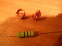
I have question about the Resistor/Inductor at the output of the Leach. The design has a custom wound inductor around the 10 Ohm resistor at he output.
I noticed that the dead amp I'm disassembling has a similar arrangement. Coil and resistor are the same values, but instead of being wrapped around the resistor, the coil sits on the circuit board vertically with the resistor right over it (perpendicular).
My question is, could I use this arrangement for the Leach (ie just reuse the 10 turn coil from the dead amp)? Is the inductor wrapped aroung the resistor just to make it easier to wrap? Any thoughts?
If it's a problem, I could just slip the coil over the new resistor, but it won't be tight (slightly larger diameter).
-b
WorkingAtHome said:
My question is, could I use this arrangement for the Leach (ie just reuse the 10 turn coil from the dead amp)? Is the inductor wrapped aroung the resistor just to make it easier to wrap? Any thoughts?
-b
The coil and resister are in paralle in Leach amp. so as long as you maintain this relationship, it does not matter if they are on top of each other or side by side.
This thread prompted me to measure the inductance of a 10-ohm rectangular cement resistor of the type commonly wirred in parrale to a output inductor. It read ~2.4 uH. That's about the value that the typical output inductor air coil has. So now I wonder if that matters or not. The stated function of the resistor is to dampen the air coil, but how well can it do that if has about the same inductance?
Hmmm . . . .
PS: very low value resistors like 5W RE resistors od .22-ohm of .047-ohm measured very low (0.1 uH) if at all.
Hmmm . . . .
PS: very low value resistors like 5W RE resistors od .22-ohm of .047-ohm measured very low (0.1 uH) if at all.
This is why I ask. The fact that it is wrapped around the resistor means that it will have some additional effect. I don;t have time right now to do any tests, but it would be interesting to find out.
I plan on trying the over/under setup first, as I have the nice little coils. If it causes problems, I can always unwind them and wrap the resistor as specified.
Thanks-
b
I plan on trying the over/under setup first, as I have the nice little coils. If it causes problems, I can always unwind them and wrap the resistor as specified.
Thanks-
b
I think this is why Leach originally specified a carbon composition resistor. They have less inductance than metal film or carbon film because they don't have a spiral path. They have less impedance at high frequencies. I think they also provided the right size exterior diameter for the inductor to wind around. Unfortunately, carbon comp resistors are not easy to find any more.
Hi,
I think the parallel resistor and inductor do two things.
1. the resistor damps the inductor to reduce ringing.
2. it provides a bypass path for hi frequencies when the inductor starts to develop significant impedance.
I think that 2 . requires a low inductance resistor. The physical relationship of the pair is unimportant. but I want to make an observation.
In my opinion the resistor is less important at audio frequencies and can have a slightly longer route to the output. Minimise inductance but don't worry about resistance.
More importantly the main current path for audio is through the inductor and here it is important to minimise resistance. A long small diameter coil has inherently a poor inductance/ resistance ratio. Much better is a coil wound around a large diameter former with the coil proportions about square and the former diameter about 2 times the coil size.eg 16mm former 8mm wide use 2.0mm wire wound in 4 layers to form 16 turns giving a coil 8mm wide and 8mm high. This will give close to minimum resistance for that inductance.
Most manufacturers ignore this and opt for the coil around the resistor presumably because they have found insufficient sound quality improvement relative to the additional cost.
regards Andrew T.
Is this resistor 1W or 2W? The one I recently got for Leach amp also measures 6.4 mm dia. and 18 mm long. According to specs here http://dkc3.digikey.com/PDF/T051/1029.pdf it should be OX ie 1W. But I ordered Leach's recommended 2W resistor for this not 1W!!! Any idea?
Any idea?- Status
- This old topic is closed. If you want to reopen this topic, contact a moderator using the "Report Post" button.
- Home
- Amplifiers
- Solid State
- Resistor/Inductor at Leach Output