Hey All ....
Is anyone interested in a generic chassis design effort ???
I've got an idea for a Amp Packaging system . Something that ANYONE can use . I've been lurking the audio boards for DIY projects and I noticed, everyone and thier brother has an idea for an amp circuit, but the hardest part about "any" of this is making it "real" . You know , the "package" . This is what I do for a day job") Well ... Mostly PCB Design lately ....
Well ... Mostly PCB Design lately ....
I've been thinking of making a "rack" system , with modules to plug in and out for different amps and power supplies . More of a heat and power management "system" to build/test audio amps in ...
The cards would/could be the power supply and different amps for different users ... i.e. home theater , 100-200 watts x6 or x7 with 250-1500w subs ??? relay card for multi-room users ??? maybe a power supply for the car stereo crowd ??? a one size fits ALL scheme ????
My idea is to have an "orderable" or "buildable" cabinet. Maybe with SOME "custom" sheet metal parts built into a rack and card system . Then PCB's could be designed to fit this system . My idea here, I think, is CHEAP !!! ... OPEN, as in, free to the public DIY groups . EXPANDABLE , expendable , economical
YES .. I want my cake and eat it too !!!!!
it could be built up as 500 watts or upto 5000 watts ??? just get the bigger heat sink and fan kits
let me know your thoughts .....
TVP
Is anyone interested in a generic chassis design effort ???
I've got an idea for a Amp Packaging system . Something that ANYONE can use . I've been lurking the audio boards for DIY projects and I noticed, everyone and thier brother has an idea for an amp circuit, but the hardest part about "any" of this is making it "real" . You know , the "package" . This is what I do for a day job
Well ... Mostly PCB Design lately ....I've been thinking of making a "rack" system , with modules to plug in and out for different amps and power supplies . More of a heat and power management "system" to build/test audio amps in ...
The cards would/could be the power supply and different amps for different users ... i.e. home theater , 100-200 watts x6 or x7 with 250-1500w subs ??? relay card for multi-room users ??? maybe a power supply for the car stereo crowd ??? a one size fits ALL scheme ????
My idea is to have an "orderable" or "buildable" cabinet. Maybe with SOME "custom" sheet metal parts built into a rack and card system . Then PCB's could be designed to fit this system . My idea here, I think, is CHEAP !!! ... OPEN, as in, free to the public DIY groups . EXPANDABLE , expendable , economical
YES .. I want my cake and eat it too !!!!!
it could be built up as 500 watts or upto 5000 watts ??? just get the bigger heat sink and fan kits
let me know your thoughts .....
TVP
I like the idea, expecially the notion of having the PSU be a component on the bus. But I doubt it is viable--have you seen the costs on these kind of plug in chassis? You could buy a complete BrianGT/Peter Daniel amp with chassis.
Check out what DIYcable is doing. Their chassis is nice and configurable, but not cheap. What you are asking for sounds a lot more complex.
Check out what DIYcable is doing. Their chassis is nice and configurable, but not cheap. What you are asking for sounds a lot more complex.
Go for it
Good idea! If you know what you are doing, that would help 99% of us out tremendously. Many of us are very interested in such a design, please tell us more!
It doesn't hurt to post your ideas and see if people are interested, give it a shot. I could use a few of these...
Good idea! If you know what you are doing, that would help 99% of us out tremendously. Many of us are very interested in such a design, please tell us more!
It doesn't hurt to post your ideas and see if people are interested, give it a shot. I could use a few of these...
Interesting. An "open source" design. You may want to consider the power connections to be wired to handle the current. Considering the different size / power ratings the case could be 0 - 100W, 100 - 500W, 500 - ?W sizes. I don't think one size would fit all.
Wouldn't it be great to mix and match voltage amp stages?
Your power supplies may be dual mono, dual secondary, with or without separate voltage amp supplies. A slide in space for the power supply might fit that bill.
This could work.
-Chris
Wouldn't it be great to mix and match voltage amp stages?
Your power supplies may be dual mono, dual secondary, with or without separate voltage amp supplies. A slide in space for the power supply might fit that bill.
This could work.
-Chris
Hey all .....
I'm heading down this path ANYWAY and I'd like to get ANY AND ALL idea's ANYONE might have !!!!! So regardless , IF you want one or not , feel free to chime in !!! AT LEAST "one" will be built !!!
I've designed over 150 chassis parts and 1000 PCBs . I've been at this for 20 years or so ... working with DC to 200 amps and multi-gigabyte digital paths ... mostly designing optical switching equipment lately . I feel that I have more than enough experience to handle this job . I also have a couple of close friends, couple that do the same thing I do, and they have expressed interest as well . Couple of them are more into Mechanical Engineering than I am . One in particular works for a fabrication rep firm This isn't something I just came up with and posted here ... I .. like ALOT of people here .... have built a few amps for hobby .. Just so happens I'm a audio/visual geek as well as a design geek .. So most of my toys are PCB based and packaged before built I've been playing with the chassis idea now for a couple of months ... thinking of something I need/want for my own use . I've been hunting for AMP schematics to get an idea of what kind of power is available to work a chassis around ... then I spotted this place .... figured others might like this idea too ???????
so as a starting place .... what does everyone want "in" this chassis ?????
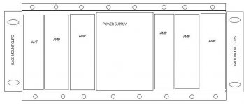
My idea is an "open cage" to slide cards in ... as simple as possible and as few "pieces" as possible .. 19" rackable .. leaves 16.5" of inside the cage room ???
make the pieces in such a way that...
tops and bottoms are the same piece ..just flipped over ???
left and right sides are the same .. only flipped over ????
optional sides can be configured to make the chassis taller .. or the cards/modules wider .... i.e. 1", 2", 3", 4" wide top/bottoms, fronts and backs for the cards/modules that all have the same side used on both the left and right ... then a chassis side piece would have a matching card/module side piece ...
Power .....
my idea here is simple ... just a "spec" for copper bar stock cut to fit the width of the chassis ... isolation mount a couple of them
in the back of the chassis . Then we have a "clip" that is soldered to the back of the module/card/PCB in a "spec" area OR MOUNTED to the module for the point to point designers ... different clips for different width modules too ... 4" wide clips would be REQUIRED for the power supply .. .5" wide clips for your 50 watt amp module ??? Also an option for OUTSIDE power .. i.e. the rack can be ALL AMPS with a totally separate PS chassis ...
HEAT ....
find an "off the shelf" extrusion that mounts on the top and/or bottom .. mount as many as you need ???
DIMENSIONS ....
how DEEP and TALL is the chassis ????? depends on ....
how much power (watts) ???
how much HEAT (BTU's) ???
how much room (real estate) do we/I need ??????
I don't think we need more than 12-14" deep ?????????
how big are the toriod xfmers ??? caps ???
I'm basing ALOT of my opinions on a Nikko Alpha 450, which I have ALOT of experience with .. only I'm assuming a MUCH HIGHER power density .. more like 2500 watts out of a
Smaller package size ...
Costs $$$$$$......
Here's the killer for the deal I guess .... I've been checking the PO's here at the "day job" for our proto chassis costs ... In qty 5-10...USING USA FABRICATORS AND ALUMINUM ... I THINK we can get the pieces around $5-40 per piece .. OBVIOUSLY , we/I need more module pieces than cage pieces , so there would be a price/qty break there .... this puts the target price around $200-350+ for a complete populated chassis . Using the China sources cuts the costs in half .. and TIN cuts another 40% ... and with say , qty 25, we can probably cut the cost another 35% !!!!!!!!! Hopefully, The design will be simple enough for the average home sheet metal guy, that he could build his own too !!!
BOM .... Bill of Materials .... IDEAS figured on the HIGH SIDE !!!!!
$50 $25 2 cage top/bottoms
$25 $12 2 cage sides
$112 $8 14 module sides
$60 $5 12 2" module top/bottoms
$16 $8 2 4" module top/bottoms
$6 $2 3 16" copper rails
$12 $2 6 isolation mounts
$60 $5 12 2" module faces
$60 $5 12 2" module backs ???? open ???
$10 $5 2 rack mount ears
$411 USA made, Aluminum ..... $150 Off shore Tin higher qty ???????
So YES, you CAN BUY AN AMP for what THIS chassis might/will cost ... I've been eyeing the cheap ($250) Crowns on eBay for quite some time too ... then I remember MY application is MY home .. 2 theaters , front and rear outsides , garage too .... those Crowns sure do get expensive when you have to buy 5 or so of them :\ which is what lead me to this idea in the first place ... I figured for the 10 cents a watt most people are spending on their home brews I could still end up way ahead ... My goal is $500 for a 2500 watt 6.1 amp , that's 250w X 6 @ 8 ohm with 500x2 for the subs ... that would be
3 x $250 and 2 x $500 = $1750 in CHEAPO USED Crowns !!!!
still wondering which DIY sub to do..... the LAB , Rog's , JBL 4550?? ... decisions....decisions.....decisions....
I'm heading down this path ANYWAY and I'd like to get ANY AND ALL idea's ANYONE might have !!!!! So regardless , IF you want one or not , feel free to chime in !!! AT LEAST "one" will be built !!!
I've designed over 150 chassis parts and 1000 PCBs . I've been at this for 20 years or so ... working with DC to 200 amps and multi-gigabyte digital paths ... mostly designing optical switching equipment lately . I feel that I have more than enough experience to handle this job . I also have a couple of close friends, couple that do the same thing I do, and they have expressed interest as well . Couple of them are more into Mechanical Engineering than I am . One in particular works for a fabrication rep firm
This isn't something I just came up with and posted here ... I .. like ALOT of people here .... have built a few amps for hobby .. Just so happens I'm a audio/visual geek as well as a design geek .. So most of my toys are PCB based and packaged before built I've been playing with the chassis idea now for a couple of months ... thinking of something I need/want for my own use . I've been hunting for AMP schematics to get an idea of what kind of power is available to work a chassis around ... then I spotted this place .... figured others might like this idea too ??????? so as a starting place .... what does everyone want "in" this chassis ?????
My idea is an "open cage" to slide cards in ... as simple as possible and as few "pieces" as possible .. 19" rackable .. leaves 16.5" of inside the cage room ???
make the pieces in such a way that...
tops and bottoms are the same piece ..just flipped over ???
left and right sides are the same .. only flipped over ????
optional sides can be configured to make the chassis taller .. or the cards/modules wider .... i.e. 1", 2", 3", 4" wide top/bottoms, fronts and backs for the cards/modules that all have the same side used on both the left and right ... then a chassis side piece would have a matching card/module side piece ...
Power .....
my idea here is simple ... just a "spec" for copper bar stock cut to fit the width of the chassis ... isolation mount a couple of them
in the back of the chassis . Then we have a "clip" that is soldered to the back of the module/card/PCB in a "spec" area OR MOUNTED to the module for the point to point designers ... different clips for different width modules too ... 4" wide clips would be REQUIRED for the power supply .. .5" wide clips for your 50 watt amp module ??? Also an option for OUTSIDE power .. i.e. the rack can be ALL AMPS with a totally separate PS chassis ...
HEAT ....
find an "off the shelf" extrusion that mounts on the top and/or bottom .. mount as many as you need ???
DIMENSIONS ....
how DEEP and TALL is the chassis ????? depends on ....
how much power (watts) ???
how much HEAT (BTU's) ???
how much room (real estate) do we/I need ??????
I don't think we need more than 12-14" deep ?????????
how big are the toriod xfmers ??? caps ???
I'm basing ALOT of my opinions on a Nikko Alpha 450, which I have ALOT of experience with .. only I'm assuming a MUCH HIGHER power density .. more like 2500 watts out of a
Smaller package size ...
Costs $$$$$$......
Here's the killer for the deal I guess .... I've been checking the PO's here at the "day job" for our proto chassis costs ... In qty 5-10...USING USA FABRICATORS AND ALUMINUM ... I THINK we can get the pieces around $5-40 per piece .. OBVIOUSLY , we/I need more module pieces than cage pieces , so there would be a price/qty break there .... this puts the target price around $200-350+ for a complete populated chassis . Using the China sources cuts the costs in half .. and TIN cuts another 40% ... and with say , qty 25, we can probably cut the cost another 35% !!!!!!!!! Hopefully, The design will be simple enough for the average home sheet metal guy, that he could build his own too !!!
BOM .... Bill of Materials .... IDEAS figured on the HIGH SIDE !!!!!
$50 $25 2 cage top/bottoms
$25 $12 2 cage sides
$112 $8 14 module sides
$60 $5 12 2" module top/bottoms
$16 $8 2 4" module top/bottoms
$6 $2 3 16" copper rails
$12 $2 6 isolation mounts
$60 $5 12 2" module faces
$60 $5 12 2" module backs ???? open ???
$10 $5 2 rack mount ears
$411 USA made, Aluminum ..... $150 Off shore Tin higher qty ???????
So YES, you CAN BUY AN AMP for what THIS chassis might/will cost ... I've been eyeing the cheap ($250) Crowns on eBay for quite some time too ... then I remember MY application is MY home .. 2 theaters , front and rear outsides , garage too .... those Crowns sure do get expensive when you have to buy 5 or so of them :\ which is what lead me to this idea in the first place ... I figured for the 10 cents a watt most people are spending on their home brews I could still end up way ahead ... My goal is $500 for a 2500 watt 6.1 amp , that's 250w X 6 @ 8 ohm with 500x2 for the subs ... that would be
3 x $250 and 2 x $500 = $1750 in CHEAPO USED Crowns !!!!
still wondering which DIY sub to do
..... the LAB , Rog's , JBL 4550?? ... decisions....decisions.....decisions....Attachments
Well, TVP, knowing that you are a seasoned designer with a good idea of the costs involved, I think you will meet with success.
The most buy-in will likely be from gainclone type designs. If the form factor can accommmadate a decent transformer and X number of 3875/4780 amps I think that it will have the best possible mass appeal. Once you have that, you might either broaden your scope to some common discrete designs or just hope that people will adapt to fit your chassis.
I don't know what the sinking requirements are of the amps you plan to pack into your chassis but you might want at least one readily sourced heatsink profile that can fit in a "standard" module. Depending on this decision the same profile in a longer length might accommadate multiple designs.
I agree
I agree with Tiroth, the design so far looks good to me.
For your slidable cards, keep in mind that a lot of people here like to make their own PCBs, so consider a way to allow for many size PCBs to work in the case, either slide in or fixed, with a common connector to connect them up.
Isn't tin good for shielding? Maybe the interior could be subdivided by a tin or other shield to make a few isolated compartments?
Hey ...
Thanks for the vote for success ...
as for the heat and sinking it .. I was planning/thinking the "case" would do ALL of it !! i.e. the amps and power supplies would transfer the heat by mounting your "switches" (fets, xstrs,etc) on the body of the "modules" which would transfer it to the "case" ... the "case" could have a heat sink mounted on it .. top and/or bottom ... as needed . Idea here is , modular .... if your design only dissapates 10 watts of HEAT , then you probably don't need a heat sink AT ALL ... but if your building a 2500++ watt monster with only 85% eff and your burning off 375 watts ... then you'll proably want to bolt on a few heat sinks and fans to help dissapate it !!!!!
Of course ... I maybe WAY off base here and you guys WANT the heatsinks (and fans??) inside the modules ... then we can knock a couple of holes in the front and push or pull air from the rear ??????
hence the reason for posting all of this to get ALL the ideas out here and MASHED out
Since I'm a PCB designer ... I was planning on repackaging SEVERAL amp designs to fit the modules ... as many as people will let me use ?!?!?!?!? and I'm MORE THAN WILLING to "front" the effort involved as well .... like I've been saying ... I plan to build MINE FIRST !!!! So if you want your amp design to fit and want a FREE PCB for putting it "out there" LET ME KNOW !!!!
Tin and isolated compartments ....
metal is metal when it comes to EMI ... of course copper connects better ..but DOESN"T last worth a DAMN !!! Lead seems to work the best .. but DON'T TOUCH IT with your bare hands !!! I don't think I've ever seen a shielded cage used in ANYITHNG but RF ??? do you guys have a requirement for that ???? Most shields I've designed solder into the PCB too ... lately we've been using solderable clips for quick removal of the shields and access to tuners/pots under the shields ... I was thinking/ planning on the larger modules having a card cage system available in the future ... (for SMPS's and BIG amp designs??) but lets say , 3-5 PCBs in the 2" and up sizes .. then one slot could be used as a isolator slot . i.e. put a "blank" PCB or hunk of metal in there to isolate 2 areas ..
I was planning on a GENERIC OPEN PUBLISHED SPEC for the PCBs, to fit the modules . Then ANYONE can make thier PCB's fit ... I'm planning on a "perferated" PCB design with the correct outline and connections for the point 2 point designers ... tube guys ??? Some people hate card sliders ... some hate stand offs ... so I've been thinking of a scheme to use EITHER !!! for stand offs , people can locate and drill thier own mounting points . Using tapered seat screws you can still have a nice flat surface on the outside . PEM's don't lend themselves to DIY'ers :\
maybe have one set of standard mouting points too ... but holes cost money ????
I'm going to be meeting with my comrades and start the CAD work soon for the chassis ... once we get a couple of things ironed out .. costs can be NAILED down better !!!
mainly .. I think ... the biggest question is how big are the transformers you guys are using ??? torioids seem to be the best thing around ... 4x5x5" seems to handle 1000 watts ????
so plan on 2 of those deep ??? 2 farad worth of caps , couple of bridges ... so 4U = 7" high or 3U= 5.25" 3U is pushing it ?? especailly when you figure in the caps, probably have to lay them down ??? or build a bank with shorties ???
KEEP THE IDEAS COMMING !!!!!!
thanx
TVP
Thanks for the vote for success
... as for the heat and sinking it .. I was planning/thinking the "case" would do ALL of it !! i.e. the amps and power supplies would transfer the heat by mounting your "switches" (fets, xstrs,etc) on the body of the "modules" which would transfer it to the "case" ... the "case" could have a heat sink mounted on it .. top and/or bottom ... as needed . Idea here is , modular .... if your design only dissapates 10 watts of HEAT , then you probably don't need a heat sink AT ALL ... but if your building a 2500++ watt monster with only 85% eff and your burning off 375 watts ... then you'll proably want to bolt on a few heat sinks and fans to help dissapate it !!!!!
Of course ... I maybe WAY off base here and you guys WANT the heatsinks (and fans??) inside the modules ... then we can knock a couple of holes in the front and push or pull air from the rear ??????
hence the reason for posting all of this
to get ALL the ideas out here and MASHED out Since I'm a PCB designer ... I was planning on repackaging SEVERAL amp designs to fit the modules ... as many as people will let me use ?!?!?!?!? and I'm MORE THAN WILLING to "front" the effort involved as well .... like I've been saying ... I plan to build MINE FIRST !!!!
So if you want your amp design to fit and want a FREE PCB for putting it "out there" LET ME KNOW !!!! Tin and isolated compartments ....
metal is metal when it comes to EMI ... of course copper connects better ..but DOESN"T last worth a DAMN !!! Lead seems to work the best .. but DON'T TOUCH IT with your bare hands !!! I don't think I've ever seen a shielded cage used in ANYITHNG but RF ??? do you guys have a requirement for that ???? Most shields I've designed solder into the PCB too ... lately we've been using solderable clips for quick removal of the shields and access to tuners/pots under the shields ... I was thinking/ planning on the larger modules having a card cage system available in the future ... (for SMPS's and BIG amp designs??) but lets say , 3-5 PCBs in the 2" and up sizes .. then one slot could be used as a isolator slot . i.e. put a "blank" PCB or hunk of metal in there to isolate 2 areas ..
I was planning on a GENERIC OPEN PUBLISHED SPEC for the PCBs, to fit the modules . Then ANYONE can make thier PCB's fit ... I'm planning on a "perferated" PCB design with the correct outline and connections for the point 2 point designers ... tube guys ??? Some people hate card sliders ... some hate stand offs ... so I've been thinking of a scheme to use EITHER
!!! for stand offs , people can locate and drill thier own mounting points . Using tapered seat screws you can still have a nice flat surface on the outside . PEM's don't lend themselves to DIY'ers :\ maybe have one set of standard mouting points too ... but holes cost money ????
I'm going to be meeting with my comrades and start the CAD work soon for the chassis ... once we get a couple of things ironed out .. costs can be NAILED down better !!!
mainly .. I think ... the biggest question is how big are the transformers you guys are using ??? torioids seem to be the best thing around ... 4x5x5" seems to handle 1000 watts ????
so plan on 2 of those deep ??? 2 farad worth of caps , couple of bridges ... so 4U = 7" high or 3U= 5.25" 3U is pushing it ?? especailly when you figure in the caps, probably have to lay them down ??? or build a bank with shorties ???
KEEP THE IDEAS COMMING !!!!!!
thanx
TVP
hey ...
why do you think the heat sinking won't work ??? I've used this scheme to dissapate over 500 watts of heat in SEVERAL designs , several times over the last few years ..... my only limitation is the fact that UL requires ANY exposed surface to be touchable ... which is max about 130 deg F ..... it would take ONE HELL of a load to heat up a OVER square foot of metal to 130 F and KEEP IT THERE !!!! right ???? add a SLIGHT breeze and it gets even harder to maintain that number !!! Now imagine if you added even the smallest heat sink !!! My 600 watt pioneer doesnt have ANYTHING near that amount of space , and no hope of air flow in my cabinet .. and no problems !!!
thanx
TVP
I think that you may be confusing output power and dissipated power. Chances are good that your 600 watt pioneer isn't dissipating more than 75 watts on an average basis. KWski is referring to class A amps and heavily biased class AB, ala Pass. Ths type of amp dissipates a lot of heat continuously, while most commercial class AB designs idle at a few tens of watts and since most people aren't going to use more than a few watts RMS, the average load is low.
My A75s have over 600 square inches of heat sink surface area per channel (10"h x 13" d x 1.5" thick, 20 fins)and have no trouble at all maintaining 55C on the heat sinks, idling at 200 W/channel.
If you are talking about a sealed chassis and trying to conduct several hundred watts off each amp and dissipate it on the chassis, your devices will get way too hot to have a useful service life. At each junction there is a thermal resistance, due to the surface not being perfectly flat. Sheet metal doesn't have enough cross section to conduct much heat efficiently. all this results in a tremendous temperature rise from the heat sink to the device junction.
Take a look at the AXE-1 calculator on the AX wiki - it includes a spot where you can add the thermal resistance of your transistor mounting scheme. Let's be really generous and say each interface has a thermal resistance of .1K/W. card-rail-case-sink is three junctions, so put .3 in that spot. Don't forget the .7 onto and .7 off the device insulator. See what that does to your junction temperatures.
The only way that I can see your idea working for class AB amps is to include ventilation and a space for each card to have its own heat sink, something like what outlaw audio does here: http://www.outlawaudio.com/products/770_gallery.html# Sealed up the way it sounds like you're heading, I agree with Kilowatski, useful for class D and low power chip amp applications only.
I'm thinking you want a standard bus connection for the card edge. One connector uses a three pin high amp connector for +V,-V,Gnd. I guess this is your buss bar idea, but should it be pluggable? could always machine copper bits that mount on the card, then screw to the bus bar from the rear with copper screws. Copper does corrode, but a tight screw connection will not corrode where is matters, not for a long time anyway.
As for heat sinking, could just add custom heat sink cards adjacent to hot modules. Can have micro fans blowing out the back or even water cooling. Pull the heat from the chassis at module edge. Maybe just make your module 2 or 3 u wide by bolting together.
Another possibility. Modules are inserted from the top. Top of enclosure uses sections - flat metal or heat sink depending on what's in a given slot. or the heat sinks can slide onto the back from the top - picture an aluminum dovetail or something on the back of the module with the devices mounted to it: slide in your mode, screw to buss bars for power, slide on the heat sink (which can couple to the adjacent module spaces to make it larger).
Speaker connections on the bus as well? Comes to a problem with how many speakers you can output to per chassis. Probably best to have speaker outs on the back of the cards.
Just stormin ideas.
-b
Forgot to mention liquid cooling. Makes me cringe too, but there are a lot of water-cooled products out there now for computers. Cooling blocks that sit right on the CPU, use a small pump, and pump to a radiator (with or without fans).
Could be the top plate or back plate is a big heat sink with water cooling built in. This keeps it sealed and away from direct contact with the devices.
-b
Could be the top plate or back plate is a big heat sink with water cooling built in. This keeps it sealed and away from direct contact with the devices.
-b
TVP,
No way on the heat sink. Do your calculations; 130 degrees F is 54 degrees C. That means your heatsink needs to support a 34 degrees C rise above ambient. If you do the division for the 500 watts that means you need a heatsink that can handle 0.68 degrees/ watt. Do you know how large of a heatsink that would take? You would need a 17" piece of the following:
No way on the heat sink. Do your calculations; 130 degrees F is 54 degrees C. That means your heatsink needs to support a 34 degrees C rise above ambient. If you do the division for the 500 watts that means you need a heatsink that can handle 0.68 degrees/ watt. Do you know how large of a heatsink that would take? You would need a 17" piece of the following:
Attachments
Hey All .,...
thermal dynamics 101
If you READ my whole thread ... I'm NOT trying to dissapate the heat across ONE LAYER of SHEET METAL ... there are ATLEAST 4 layers of sheet metal there ... and an offer of a heat sink for the top AND the bottom not to mention fans??? and why do you THINK you can't dissipate 375 watts ACROSS a SQUARE FOOT ????? you know .. that's the CROSS SECTION in this application ??? I'm not cutting the sheet metal into strips and trying to tranfer the heat from one edge to another edge .. I'm trying to tranfer the heat from ONE FLAT SIDE OF THE SHEET TO THE OTHER FLAT SIDE ... right ????
ahhh ... no ... I'm NOT confused ... I was on the team of poeple that managed to put a 100 gig optical router hanging out on a telephone pole ... SOMETHING ALL THE EXPERTS IN THE WORLD SAID IS IMPOSSIBLE ...yet they have been hanging there and running for OVER 4 years !!! I often do the impossible .. every day infact ... oh , and BTW .. it's dissapating 118 watts of HEAT in the NV AZ Sun AND you can touch the case !!! look ma no FANS either !!!
so your saying your A75's aren't UL listed ?? i.e. 30 deg C is the MAX allowed case temp from UL ... or are you saying they are 55 d C AT the transistor ??? and get cooler from there ??? they idle burning 200 watts of HEAT or even 200watts or 110 line AC ???? holy **** bat man ... what are they total power rated !!!!
so a car can't dissapte 250k ++++ BTU's (500kw++) through a single layer sheet metal radiator ???? heat dissapation is a matter of square inches of dissapation area ... more sq inches = more heat transfer !!!
unless you guys are talking (behind my back) about putting 3-4kw with 80% eff into this chassis .. I really don't think heat is the issue to be concerned about ...
size is the problem right now .....
power ....
yes the idea is a bus bar here .."just" a simple piece of copper or brass or whatever (gold plated.. I'm thinking of a peice of 1/4" stock with a U shaped clip (on the module) that wraps around 3 sides of it ... running the WHOLE width of the module ... sounds like we need 5 supply rails ... 3 high current , higher voltage .. with 2 small rails for the lower voltages ????
short of 3-4kw I don't think we'll need a water system on this either ... don't cringe .. they use that almost exclusively on ion gas lasers .. Argon , Krypton etc ... with a VERY HIGH VOLTAGE AND CURRENT SUPPLY !!! a heat pipe or freon system would accomplish the same goal without the electrocusion hazard
other ideas I've been tossing around ...
spring load the bottom of the chassis so the modules have some tension on them ... this increases the thermal transfer rate ... simluar idea for the front to rear of the modules .. this puts pressure on the power rails and increases the electrical power transfer rating as well ....
keep 'em comming ........
thanx
TVP
thermal dynamics 101
If you READ my whole thread ... I'm NOT trying to dissapate the heat across ONE LAYER of SHEET METAL ... there are ATLEAST 4 layers of sheet metal there ... and an offer of a heat sink for the top AND the bottom not to mention fans??? and why do you THINK you can't dissipate 375 watts ACROSS a SQUARE FOOT ????? you know .. that's the CROSS SECTION in this application ??? I'm not cutting the sheet metal into strips and trying to tranfer the heat from one edge to another edge .. I'm trying to tranfer the heat from ONE FLAT SIDE OF THE SHEET TO THE OTHER FLAT SIDE ... right ????
ahhh ... no ... I'm NOT confused ... I was on the team of poeple that managed to put a 100 gig optical router hanging out on a telephone pole ... SOMETHING ALL THE EXPERTS IN THE WORLD SAID IS IMPOSSIBLE ...yet they have been hanging there and running for OVER 4 years !!! I often do the impossible .. every day infact ... oh , and BTW .. it's dissapating 118 watts of HEAT in the NV AZ Sun AND you can touch the case !!! look ma no FANS either !!!
so your saying your A75's aren't UL listed ?? i.e. 30 deg C is the MAX allowed case temp from UL ... or are you saying they are 55 d C AT the transistor ??? and get cooler from there ??? they idle burning 200 watts of HEAT or even 200watts or 110 line AC ???? holy **** bat man ... what are they total power rated !!!!
so a car can't dissapte 250k ++++ BTU's (500kw++) through a single layer sheet metal radiator ???? heat dissapation is a matter of square inches of dissapation area ... more sq inches = more heat transfer !!!
unless you guys are talking (behind my back) about putting 3-4kw with 80% eff into this chassis .. I really don't think heat is the issue to be concerned about ...
size is the problem right now .....
power ....
yes the idea is a bus bar here .."just" a simple piece of copper or brass or whatever (gold plated
.. I'm thinking of a peice of 1/4" stock with a U shaped clip (on the module) that wraps around 3 sides of it ... running the WHOLE width of the module ... sounds like we need 5 supply rails ... 3 high current , higher voltage .. with 2 small rails for the lower voltages ????short of 3-4kw I don't think we'll need a water system on this either ... don't cringe .. they use that almost exclusively on ion gas lasers .. Argon , Krypton etc ... with a VERY HIGH VOLTAGE AND CURRENT SUPPLY !!!
a heat pipe or freon system would accomplish the same goal without the electrocusion hazard other ideas I've been tossing around ...
spring load the bottom of the chassis so the modules have some tension on them ... this increases the thermal transfer rate ... simluar idea for the front to rear of the modules .. this puts pressure on the power rails and increases the electrical power transfer rating as well ....
keep 'em comming ........
thanx
TVP
I sorry to be a wet blanket on the whole thing but, there were a number of commercial card bassed amp systems running arround the pro market in the early eighties. Currently a lot of fire evac systems run on card bassed systems.
Some of these systems wer designed for flexibility of installation .... option. ect. others were designed for rapid field replacement of faulty modules.
My impression has been
1. That all the fiddle & modules..... are much more bother and much more expensive than starting from scratch. Afterall all you need is a transformer, bridge, a few big caps, an amp pcb or two & some heat sink... oh add some connectors.
2. all the modularising stuff introduces "trouble" extra connectors all the stuff you don't need and most " audiophiles" are trying to minimise.
3. every now & then these ideas pop up & even get to market & disapear just as fast.
I have seen quite a bit of audio stuff that "looks" like it was designsed by somebody with a background in heavy comm's or instrumentation & thats all very nice & the workmanship in design is wonderfull. But its wasted on audio power amps.
There are heaps of transformers out there, they come with their mounting hardware.
A 35 amp bridge is a simple common part & mounts with one bolt.
Biiiggg caps come with mounting gear, easy.
All the electronics can go on one board & you hang that off your heatsink.
Screwing it into a rack box is a very simple task.
Sorry fellas I think its a waste of time & brain power.
200 watts per channel is a lot of heat. That was my point about class A operation - you're lucky to get 50% efficiency. The Pass Alephs go around 33%, Zens can be 5% efficient. Some of us think that the sound quality of class A operation is worth the heat. My 200 watts (400 W stereo) idle gets me 50 watts out if I limit it to class A, maybe 150 if I go AB, since my rail voltages are higher than prescribed.
No, I don't try for a UL rating on my DIY projects, although I follow practices to make them safe. You CAN touch my cases, but not for long.
Even spreading your heat across the flat surface, you've got a couple of interfaces to cross - grease will help but the larger surfaces make it that much harder to get it flat across the width, even for a professional machine shop.
Your router probably has its power devices mounted directly to the inside surface of the case, and they are massively parrallel - lots of devices carrying the load mean the junction to sink thermal resistances parallel, just like electrical resistors. Even so, I suspect that you are probably pushing the junction temperatures a bit higher than the DIY reliability "limit" of 100 C in the summer sun. Nothing wrong with that, just don't expect it to live 20+ years. Again, I refer you to the AXE-1 spreadsheet to see the effect adding more devices in parallel has on junction temperatures.
Heat dissipation capability is a function of surface area AND mass flow across it and the thermal capability of the medium to which you dissipate the heat. you need more area in space, since there is no convection.
Here's a problem I was part of a team that solved: Dissipate 5KW on VME format cards at 70,000'. Don't forget ram air temperature rise. You need a fan for low speed/altitude ops, but at high altitude, the fan will impede the airflow. You're not the only one who has worked on some difficult problems. People smarter than me did the solving, I can regurgitate the solution, but I'll probably miss some important detail.
lowlevel has an excellent point - in a production system requiring flexibility and (field) upgradability, the card bus makes sense. However, in a one off (or even ten off) project it's just a lot of expense with no real benefit and maybe even a detriment. It's way too easy for us engineer types to get carried away with the "wouldn't it be cool if..."
- Status
- This old topic is closed. If you want to reopen this topic, contact a moderator using the "Report Post" button.
- Home
- Amplifiers
- Solid State
- Generic Open Chassis Design ...