Hi All,
In the Sulzer and Pooge 5.1 power supply regulator circuit diagrams as posted in this forum, there is a zener diode specified:
MMSZ6V8T1
Anyone know what the specs on this is since I am probably going to have to find a substitute, preferable not surface mount.
Many thanks
Ryan
In the Sulzer and Pooge 5.1 power supply regulator circuit diagrams as posted in this forum, there is a zener diode specified:
MMSZ6V8T1
Anyone know what the specs on this is since I am probably going to have to find a substitute, preferable not surface mount.
Many thanks
Ryan
MMSZ6V8T1
http://onsemi.com.cn/pub/Collateral/DataSheet/mmsz2v4t1.pdf
Use the LM329, it is much better than a zener.
http://www.national.com/ds/LM/LM129.pdf
H.H.
http://onsemi.com.cn/pub/Collateral/DataSheet/mmsz2v4t1.pdf
Use the LM329, it is much better than a zener.
http://www.national.com/ds/LM/LM129.pdf
H.H.
Re: sulzer circuit
Search the threads on the subject of these supplies - couple of weeks ago I think. IF the problem is layout related, it most probably is due to bad grounding strategy. Rigouresly (is that spelled right?) keeping to star grounds, not sharing multiple returns in a single wire often solves layout related problems.
Jan Didden
ced said:Does anyone perchance have the board layouts (and if possible a stuffing guide) for the sulzer circuit? I rustled up one and although it worked fine it sounded terrible- no dynamics etc etc. which I suspect was down to layout
Ced
Search the threads on the subject of these supplies - couple of weeks ago I think. IF the problem is layout related, it most probably is due to bad grounding strategy. Rigouresly (is that spelled right?) keeping to star grounds, not sharing multiple returns in a single wire often solves layout related problems.
Jan Didden
Sulzer layout
Jan,
A few years ago you wrote an article on The Audio Amateur with a clever and simple DAC using an LCR filter.
On that project you implemented a Sulzer supply where you used large capacitors at the output. 10.000uF if I'm not wrong.
But on the latest Jung/Didden/Galo version it was suggested as a no-no using more than 120uF output capacitors or the circuit might oscillate.
Did you see any oscillation on that circuit of yours?
BTW: back then I had been thinking of using star connections for ground, V+ and V- tracks, and you were one of the first designers that implemented such tracking on a serious project.
How far does it go this star connecting? Should it be applied as much as possible? Where?
Carlos
Star Grounding
Jan,
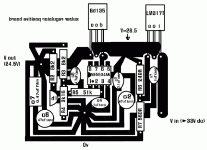
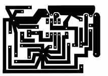
thanks for the tip. I've tried redesigning a positive sulzer board as you suggested with rigorous (think that is the way it's spellt) star grounding and was wondering if you (or anyone else) might comment on it. Is this what you were thinking of or does it have any obvious faults? If it seems ok I'll cook one up in the next couple of weeks and see if that works.
It uses a tracking prereg providing 4V headroom for the circuit, outputs 24.5 V and has R2 matched to R3 as I read somewhere that it aids DC stability and drift. Output transistor is a bd135 but that should be ok, shouldn't it? D1 is the LM329cz.
Cheers
Cedric
Attachments
- Status
- This old topic is closed. If you want to reopen this topic, contact a moderator using the "Report Post" button.
- Home
- Amplifiers
- Solid State
- Sulzer Reg-Source or substitute for MMSZ6V8T1 zener

