Here's what I am looking for:
A N channel power mosfet that is linear around 2A of Drain current and 40vdc supply voltage.
Bias voltage 2-4 volts or so.
will be running into a 64:8 Z transformer.
So far:
BUZ900P
2SK1529
2SK135
I think these are all lateral mosfets.
IS there an IR part that could work?
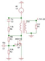
The attached image is of the output stage.
A N channel power mosfet that is linear around 2A of Drain current and 40vdc supply voltage.
Bias voltage 2-4 volts or so.
will be running into a 64:8 Z transformer.
So far:
BUZ900P
2SK1529
2SK135
I think these are all lateral mosfets.
IS there an IR part that could work?
The attached image is of the output stage.
Attachments
how about...
Or there is the Exicon EC10N16/20 which looks very promising.
Any data sheets for this?
Thanks!
Or there is the Exicon EC10N16/20 which looks very promising.
Any data sheets for this?
Thanks!
yeah....
yes i am.
simulates good with a p channel buffer mosfet driving the n-channel stage.
good for 12W RMS into 8 ohms.
power supply thinking of:
33V/5A transformer
100v/50A bridge rectifier
2 50v/10,000uf caps
2mH air core inductor
then 2 50v/10,000uf caps
per channel
The p-channel buffer will have its own pi filter taken from the above mentioned bridge.
comments?
The Exicon MOSFETs are nice. They do have datasheets on their website, although they contain limited data.
I have a spice model for ECF20N25 which you may find useful. Maybe not the exact one you're looking for, but they all behave similarly. Exicon will probably send you more data if you ask them.
I have a spice model for ECF20N25 which you may find useful. Maybe not the exact one you're looking for, but they all behave similarly. Exicon will probably send you more data if you ask them.
Code:
.SUBCKT  ECF20N25 1 2 3
**********************************************
*      Model Generated by PEDC               *
*Copyright(c) Power Electronics Design Centre*
*         All Rights Reserved                *
*   Power Electronics Design Centre          *
*   Dept of Elec & Electronic Engineering    *
*   University of Wales Swansea              *
*   Singleton Park                           *
*   Swansea SA2 8PP                          *
*   Tel : +44 (0)1792 295420                 *
*   Fax : +44 (0)1792 295686                 *
*   E-mail : [email]pedc@swansea.ac.uk[/email]              *
**********************************************
* Model generated on Dec 9 1999
* MODEL FORMAT: SPICE Level 1
* External Node Designations
* Node 1 -> Drain
* Node 2 -> Gate
* Node 3 -> Source
*
*
*
*                                     O [1]
*                                     |
*                                     Z
*                                     Z Rd
*                                     Z
*                                 D2  |
*                           Cdg0  |\ || [9]
*                           |-||--| >|O---O-----|--------|
*                           |  [4]|/ ||   |     |        |
*               [2]   Rg    |    ||---|   Z    ---     __|__
*               0--/\/\/\/\-O----|| M1    Z    / \D1   _____
*                           |[7] ||---|   Z    ---       |Cds0
*                           |         |   Z     |        |
*                           |    Cgs0 |   |RDS  |        |
*                           |-----||--O---O-----|--------|
*                                     | [8]
*                                     |
*                                     O
*                                     |
*                                     Z
*                                     Z Rs
*                                     Z
*                                     |
*                                     O [3]
M1 9 7 8 8 MM L=1 W=1
* Default values used in MM:
* With the exception of Cgs0 the capacitances are
* added externally
* Other default values are:
*   RS=0 RD=0 LD=0 CBD=0 CBS=0 CGBO=0
.MODEL MM NMOS LEVEL=1 IS=1e-32 CGSO=1.57e-9
+VTO=0.414 LAMBDA=0.104 KP=2.808
RS 8 3 0.191
D1 8 9 MD
.MODEL MD D IS=1.0e-32 N=50 BV=250
+CJO=1.54e-9 VJ=0.633 M=0.479
RDS 8 9 1e+06
RD 9 1 0.289
RG 2 7 13.3
* Drain Source capacitance Cds0
CAP1 9 8 403e-12
*************************
* Gate Drain capacitance Cdg0
CAP 7 4 25.6e-12
*************************
* Gate Drain Capacitance Cdgj0
* Modelled as a diode
D2 4 9 MDD
.MODEL MDD D IS=1e-32 N=50
+CJO=137e-12 VJ=0.7 M=0.5
*************************
.ENDSA Nemesis project seems fun, output transformers are a pretty good idea.
IR only has HEXFETS in ther line today, i think something like the IRFP240 would work well if You can use a TO 247 device, as i recall the BUZ 900 is TO3 ? As r-d/s is of lesser importance with the ot the Magnatec devices could be an option. Has been hailed as very good and, i think, still carries TO 3 parts.IS there an IR part that could work?
nope...
i tried that model... its way off what a 2SK135 or equiv would be.
the ECN 10N16 line is supposed to be like the 2SK135 or the 2SK1058...
that is what I need.
i tried that model... its way off what a 2SK135 or equiv would be.
the ECN 10N16 line is supposed to be like the 2SK135 or the 2SK1058...
that is what I need.
hmm...
i don't think anything else will work... other mosfets get very non-linear around this operating point.
btw, whats the difference between the BUZ900 series and the Exicon 10N16 line???
the datasheets look identical.
i don't think anything else will work... other mosfets get very non-linear around this operating point.
btw, whats the difference between the BUZ900 series and the Exicon 10N16 line???
the datasheets look identical.
Re: yeah....
Why do you need the buffer to drive it? Or are you just looking to use the buffer as a unity gain preamp?
Sure. Thought of using batteries instead of an AC supply? 😀
se
AudioGeek said:yes i am.
simulates good with a p channel buffer mosfet driving the n-channel stage.
Why do you need the buffer to drive it? Or are you just looking to use the buffer as a unity gain preamp?
power supply thinking of:
33V/5A transformer
100v/50A bridge rectifier
2 50v/10,000uf caps
2mH air core inductor
then 2 50v/10,000uf caps
per channel
The p-channel buffer will have its own pi filter taken from the above mentioned bridge.
comments?
Sure. Thought of using batteries instead of an AC supply? 😀
se
buffer...
well... it will make driving it easier...
47K input impedance instead of 1K or so...
improves HF response etc...
also, by adjusting how much current i have through the P channel buffer... i may be able to have some distortion cancellation.
hmm... 3 12V batteries per channel.... at least 10A/h they are pretty large and expensive.
yes i have thought about it and have built a power follower (12v supply at 4.5A bias current)... best midrange i have EVER heard in a SS amp.
anyways....
should 33vac be enough for a 40v supply at 2A?
Re: buffer...
Yeah, some sources would definitely have a problem with that.
Apparently ElectraPrint is selling a "passive preamp" that uses a 1:8 step-up trasnformer with a 10k pot across its secondary. Has an input impedance of just 150 ohms. Don't know what source components they expect someone to drive that load with. 🙂
Aye.
Alas.
Yeah, I've had very good results with battery power so far and soon I hope to have my system completely off the grid soon.
It should as long as the transformer's around 100VA or so.
Good luck!
se
AudioGeek said:well... it will make driving it easier...
47K input impedance instead of 1K or so...
Yeah, some sources would definitely have a problem with that.
Apparently ElectraPrint is selling a "passive preamp" that uses a 1:8 step-up trasnformer with a 10k pot across its secondary. Has an input impedance of just 150 ohms. Don't know what source components they expect someone to drive that load with. 🙂
improves HF response etc...
also, by adjusting how much current i have through the P channel buffer... i may be able to have some distortion cancellation.
Aye.
hmm... 3 12V batteries per channel.... at least 10A/h they are pretty large and expensive.
Alas.
yes i have thought about it and have built a power follower (12v supply at 4.5A bias current)... best midrange i have EVER heard in a SS amp.
Yeah, I've had very good results with battery power so far and soon I hope to have my system completely off the grid soon.
anyways....
should 33vac be enough for a 40v supply at 2A?
It should as long as the transformer's around 100VA or so.
Good luck!
se
heres what i got so far:
first a hammond 167T36 its a 36v/ 12A power transformer.. going to use this for both channels.
Then either a bridge rectifier or some discretes.. dunno which yet.
Then 2 50V / 10,000uf caps DK P6939-ND
Then a 6.8mH air core Solen with 1ohm DCR
Then 2 more of those caps.
this is per channel.
The input stage is powered by a LT317 with 40v input and 30v output at 40mA.
comments?
hey
anyone else got any suggestions???
Also, Is running the output mosfets at 40v 2A too high???
I do have a large heatsink...
Thanks!
anyone else got any suggestions???
Also, Is running the output mosfets at 40v 2A too high???
I do have a large heatsink...
Thanks!
i like to continue this thread
well i changed my opt i think to a 40:8 seemed better match than 64:8
any spice models for EC10N16/20 ??
i am simulating with a MSK135 model which is hard to come by physically.
any suggestions for PS??
Thanks!
well i changed my opt i think to a 40:8 seemed better match than 64:8
any spice models for EC10N16/20 ??
i am simulating with a MSK135 model which is hard to come by physically.
any suggestions for PS??
Thanks!
Came across some more Exicon models. No ECF10N16 though.
Code:
.SUBCKT ECF10N20 1 2 3
**********************************************
*      Model Generated by PEDC               *
*Copyright(c) Power Electronics Design Centre*
*         All Rights Reserved                *
*   Power Electronics Design Centre          *
*   Dept of Elec & Electronic Engineering    *
*   University of Wales Swansea              *
*   Singleton Park                           *
*   Swansea SA2 8PP                          *
*   Tel : +44 (0)1792 295420                 *
*   Fax : +44 (0)1792 295686                 *
*   E-mail : [email]pedc@swansea.ac.uk[/email]              *
**********************************************
* Model generated on Dec 6 1999
* MODEL FORMAT: SPICE Level 1
* External Node Designations
* Node 1 -> Drain
* Node 2 -> Gate
* Node 3 -> Source
*
*
*
*                                     O [1]
*                                     |
*                                     Z
*                                     Z Rd
*                                     Z
*                                 D2  |
*                           Cdg0  | \|| [9]
*                           |-||--|  >|O---O-----|
*                           |     | /||   |     |
*               [2]   Rg    |    ||---|   Z    ---
*               0--/\/\/\/\-O----|| M1    Z    / \D1
*                           |[7] ||---|   Z    ---
*                           |         |   Z     |
*                           |    Cgs0 |   |RDS  |
*                           |-----||--O---O-----|
*                                     | [8]
*                                     |
*                                     O
*                                     |
*                                     Z
*                                     Z Rs
*                                     Z
*                                     |
*                                     O [3]
M1 9 7 8 8 MM L=1 W=1
* Default values used in MM:
* The capacitances are added externally
* Other default values are:
*   RS=0 RD=0 LD=0 CBD=0 CBS=0 CGBO=0
.MODEL MM NMOS LEVEL=1 IS=1e-32
+VTO=0.635 LAMBDA=0.11 KP=2.376
RS 8 3 0.427
D1 8 9 MD
.MODEL MD D IS=1.0e-32 N=50 BV=250
+CJO=1.0e-9 VJ=0.7 M=0.5
RDS 8 9 1e+06
RD 9 1 0.62
RG 2 7 80
* Gate Source capacitance Cgs0
CAP1 7 8 480e-12
*************************
* Gate Drain capacitance Cdg0
CAP 7 4 12.2e-12
*************************
* Gate Drain Capacitance Cdgj0
* Modelled as a diode
D2 4 9 MDD
.MODEL MDD D IS=1e-32 N=50
+CJO=75.4e-12 VJ=0.174 M=1
*************************
.ENDS ECF10N20- Status
- Not open for further replies.
- Home
- Amplifiers
- Solid State
- Help with MOSFET selection