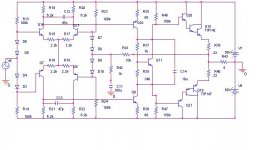
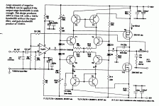
> something like this?
Never seen it done like that.
Without the stack-o-diodes, and with two long-tail current-sources for the input pairs, it is an old idea sometimes attributed to Dan Meyer.
Such ideas keep coming up. Some excellent designs are like this. And the symmetric elegance is seductive. Yet many (even most) very fine amps are built without push-pull differential.
The killer issue is setting a stable current in the second stage, your Q10 Q9, with variations in parts and temperature. At a glance, I suspect yours works better in a simulator than it will with real transistors of various Betas. (The fact that R19/R35 is about the same as a typical Beta suggests that if you change transistor, you have to change the R19/R35 ratio, which is unproducable.)
What do R46 R47 do for you?
I see C12 C13 and wonder if that is enough frequency compensation to be stable, especially when current and Ft in Q10-Q19 is wandering all over the place. It is customary to take some capacitor feedback around the 2nd and buffer stages to keep their phase response predictable in the face of changes. Your system may well work, or may work with an ideal resistor.
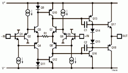
I have seen that done before. In particular, I remember reading an article in Electronics and Wireless World some years ago with such a differential in it as part of an amp with extremely high slew rate. I think it was one of a number of alternative methods given to set the current in the differentials rather than the normal current sources.
many modern high speed voltage op amps are derived from their current mode cousins by adding a push-pull buffer to the low impedance negative input resulting in a balanced push-pull differential stage
i believe a japanese researcher created a variation he called a "Diamond differential" input stage in a mid 80's jaes article
LT1794 op amp simplified circuit:
i believe a japanese researcher created a variation he called a "Diamond differential" input stage in a mid 80's jaes article
LT1794 op amp simplified circuit:
Attachments
jcx said:
i believe a japanese researcher created a variation he called a "Diamond differential" input stage in a mid 80's jaes article
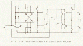
Yes, I've seen it from Sansui in the eighties. They called it a diamond differential. They used it as a second stage in a fully balanced amplifier (BTL), using all 4 collector outputs. The first stage was a simple JFET differential, driving the diamond. I think I have an AES preprint somewhere describing it.
Steven
Found it back: "Fully balanced bridge amplifier", Susumu Takahashi and Susumu Tanaka, Sansui Electric Company, Ltd., Tokyo, Japan. AES preprint 1918, presented at 72nd Convention 1982, Anaheim ,California.
I did not scan the complete preprint, only the actual diagram. In the text it is called "diamond differential circuit".
Steven
I did not scan the complete preprint, only the actual diagram. In the text it is called "diamond differential circuit".
Steven
Attachments
Hi !
I would say, this one is very sensitive to fluctuations from PSU, as
current through diodes changes with supplyvoltage, changing the
bias through the diffamps. (You could replace the resistors with ccs)
You could replace the bjts in the diffamps with jfets, not needing
the bias-stuff with the diodes. I already tried that, works very fine !
(With amazingly stable currents, giving high psrr)
The jfets work without the diodes because of their ability to work
with negative Vgs for currents below Idss. So you get pefectly
balanced symetrical input !
Mike
Mike, is it possible to look at this your schematics?MikeB said:I already tried that, works very fine !
Does "tried" mean that you have rejected such amp later?
Andrew
anli said:
Mike, is it possible to look at this your schematics?
Does "tried" mean that you have rejected such amp later?
Andrew
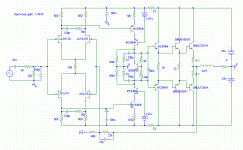
Yes, i rejected it later, but this was before i knew how to "cure"
the problem with bright sounding amps... That was the reason
why i rejected the topology, not knowing better.
Except the bright sounding everything else was "perfect".
Attached is a circuit how i would build it today, but i have not
exactly built this one, the vas is different now...
The vas in the rejected one was without rloads to the vas and
without cascodes. Also i no longer use cdoms in my latest amps...
I think i will try this one later. It's seems the only way to get perfect
symetrical currents in a LTP. In sims, DC-offset for openloop (!!!) is
30mv, closed loop down to 6.4uv. (Without DC-blocking cap)
In real world of course it will be impossible to match the jfets this
closely...
The current through the LTP is determined by the 150ohm and the
idss of the choosen jfets. For higher power the jfets needs to be
cascoded of course...
The THD of this circuit is ~0.008% with 20khz swing ~12volts.
Mike
Attachments
Hi anli !
The "cure" are the 2 100k in the vas, reducing the gain of vas and
increasing openloopbandwidth.
No i haven't tried the "TDBDC", as with jfets it was not necessary...
Somehow i believe, jfets in LTP are a nice thing. And i am not the only
one believing this... (like upupa ?)
Mike
The "cure" are the 2 100k in the vas, reducing the gain of vas and
increasing openloopbandwidth.
No i haven't tried the "TDBDC", as with jfets it was not necessary...
Somehow i believe, jfets in LTP are a nice thing. And i am not the only
one believing this... (like upupa ?)
Mike
Try this one: 2N5199 !
I have read an opinion about these symetrical LTP designs,
and a wise man has told that the asymmetrical version
produced ~half amount of distortion with the same conditions
against the "push-pull" configuration, so i think we must be
carefull with these symmetrical designs !
Off:
MikeB please tell me about those RCs in the LTPs.
Is this a theory-based solution or the practice forced you to do this ?
darkfenriz said:hallo
Have you ever used (or considered) something like this ?
seems to cancel some distortion compared to CFB, doesn't it?
Very fine circuit, hold on!
I guess that Pavel Macura's new correction amp topology was used to design it?
Anyway have you built it yet?
How does it sound?
Using darlingtons at the output might be a not completly a good idea, might spoil the sound, why did you use them?
Re: Try this one: 2N5199 !
Yes, your r46/47 do the same job, but you should use them against ground,
or you introduce ripple from the powersupply into the vas.
And yes, the 1.87volts are measured from my green leds fed with 2ma.
But i only posted the schematic because of the LTP, showing what
i meant with using jfets in this configuration. It gives constant
current through the LTP, and the absence of any ccs gives excellent
cmrr. (In theory)
Also partsnumber is greatly reduced.
In practice, when switching off this amplifier, it kept playing undistorted
until voltage reached some ~5volts, then it suddenly went silent.
This shows how stable the current through the LTP must be.
I rejected this topology earlier, as i was not sure what caused the
bright sound. Except the bright sound, the amp sounded pretty
good, even the bright sound was not really annoying, simply wrong.
No, it's not theory, it's practice. I make feedbackcompensation this
way to avoid cdoms. Seems to sound sweeter, and in sims gives
better results for higher freqs.
The dominant pole for this configuration is ~31mhz, which seems
pretty high for me.
Mike
darkfenriz said:
R46 & R47 in my schematic and Mike's 2 100k resistors to the ground are virtually the same, aren't they?
Mike- how do you get these 1,87V voltage sources? with LEDs or something
Yes, your r46/47 do the same job, but you should use them against ground,
or you introduce ripple from the powersupply into the vas.
And yes, the 1.87volts are measured from my green leds fed with 2ma.
But i only posted the schematic because of the LTP, showing what
i meant with using jfets in this configuration. It gives constant
current through the LTP, and the absence of any ccs gives excellent
cmrr. (In theory)
Also partsnumber is greatly reduced.
In practice, when switching off this amplifier, it kept playing undistorted
until voltage reached some ~5volts, then it suddenly went silent.
This shows how stable the current through the LTP must be.
I rejected this topology earlier, as i was not sure what caused the
bright sound. Except the bright sound, the amp sounded pretty
good, even the bright sound was not really annoying, simply wrong.
Cortez said:
MikeB please tell me about those RCs in the LTPs.
Is this a theory-based solution or the practice forced you to do this ?
No, it's not theory, it's practice. I make feedbackcompensation this
way to avoid cdoms. Seems to sound sweeter, and in sims gives
better results for higher freqs.
The dominant pole for this configuration is ~31mhz, which seems
pretty high for me.
Mike
witaj padamiecki rodaku
nietety moje projekty zwykle koñcz¹ swój ¿ywot na kartce lub w spicie
aktualnie jeden cierpliwie oczekuje na p³ytkê..
na razie
hi thanh
well I could give a big cap parellel to these diodes
hi MikeB
in reality I consider a regulated supply for diffy+vas and unregulated for O/P
besides.. it is hard to say why I'd rather give these resistors to rails, but I would
JFETs do seems better in this configuration I agree
THANKS FOR REPLIES
BEST WISHES FOR 2005
- Status
- This old topic is closed. If you want to reopen this topic, contact a moderator using the "Report Post" button.
- Home
- Amplifiers
- Solid State
- A push-pull differential stage- why not?