Hi all
If an output amp of say 200 W into 8 ohms is wanted and I would like to use BJT's. How schould I go about designing the output stage to get within the limits of the SOA ?
Scould I go :
1 : lots of transistors in parallel
2 : 2 or more in series
What is the better solution ?
Please help
\Jens
If an output amp of say 200 W into 8 ohms is wanted and I would like to use BJT's. How schould I go about designing the output stage to get within the limits of the SOA ?
Scould I go :
1 : lots of transistors in parallel
2 : 2 or more in series
What is the better solution ?
Please help
\Jens
Re: SOA for BJT
They make a high quality semis
compared to Europe, them Japanese People
I like them!
the japanese woman makes me want her, too
Motorola, YESJensRasmussen said:The amp is only to be used in non briged mode, with rails of about 65 Volts (+-).
Transistors are MJL3281A/MJL1302A from ON (Former Motorola I think)
Thanks
\Jens
They make a high quality semis
compared to Europe, them Japanese People
I like them!
the japanese woman makes me want her, too
warning -- I don't really know enough about this to give more than my best attempt, so take this with a grain of salt. Hopefully someone who knows more about SOA will jump in.
I would use parallel devices becasue teh real impedance of 8 Ohm speakes is likely to be somewhat less (perhaps a lot less) than 8 ohms at some frequencies, so you might get wuite a bit more current than 65V/8 Ohms.
Then to check SOA, look at page 4 of the MJL1302A data sheet, figure 13.
Unfortunately the SOA plot is on log-log scales, which makes it more trouble ... but you can plot a bunch of points on the line
I=0.5*(1/8)*(65-V)
(the 0.5 from using parallel devices)
Although that is really a line it will be a curve on the log-log plot.
If the curve crosses SOA limit you have to use series devices as well.
Why not just play it safe and use 4 of each, 2 series * 2 parallel per channel?
To mirlo
Thanks...
I was planning to use 5 transistors in parallel, since the BC voltage if the MJL3281/1302 is rated at 200 V there is no problem there. And the transistors will work at currents where Betadrop has not started yet.
Also i find it harder to design the output with transistors in series.
I would like to use a standard darlington confuration since it's problably the only one that's really suited for parallel cofigurations.
How does that sound ?
\Jens
How does it sound?
You have to tell us, when it's done!
I suspect that 5 parallel is more than enough without series, but I'd go through the process of drawing that load line with scale factor 1/5 instead of 1/2 anyway.
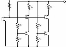
What I meant to suggest from the Bryston schematics isn't the tricky NPN+PNP per side output stage but the voltage divider thing they use in their higher output amps, would be something like this if translated to Darlington:
You have to tell us, when it's done!
I suspect that 5 parallel is more than enough without series, but I'd go through the process of drawing that load line with scale factor 1/5 instead of 1/2 anyway.
What I meant to suggest from the Bryston schematics isn't the tricky NPN+PNP per side output stage but the voltage divider thing they use in their higher output amps, would be something like this if translated to Darlington:
Attachments
Non Bridged
Hi Jocko Homo
Well to be honest I didn't really think to much about bridging, are there any obivios resons to choose bridge over non bridged ?
I mean ofcause the rails can be lower, meaning less heatloss, I guess that's one up for bridging, but how are the specs of briged amps ? I'm thinking twice the THD or something like that.
I'm not that experienced (this is the first design I do from scrach)
But given a good enough reason I will deffently think about making it in a way that enables bridge mode. - I think that the given output configuraion with 5 transistors in parallel will be ok for 2 ohm loads
\Jens
JensRasmussen said:Hi all
If an output amp of say 200 W into 8 ohms is wanted and I would like to use BJT's. How schould I go about designing the output stage to get within the limits of the SOA ?
HI Jens. This is how I understand it, but if someone will refine my understanding then please do!
Worst case is if the load is purely inductive so the current lags 90 deg behind the voltage. Assume the inductive reactance is 8 ohms. With 64 volt rails the peak current will be 64 volts / 8 ohms = 8 amps. Seeing the peak of the current happens at the zero crossing of the voltage (picture current at the lower peak of the sinewave but the voltage is ahead by 90 deg so it is passing through 0v on it's way to +64v) that means the upper transistor has the full 8 amps current
 AND the full 64 volts of the upper rail across it!!! That's 512 watts! Look at the SOA graph for your transistor and see how much current it will handle at 64 volts. When you have stopped crying, strap together as many transistors as you need. Of course all the foregoing assumes you are never going to short circuit the speaker wires etc so you don't need any margin.
 GP.
Refinement for CICLOTRON, circuling electrons-Right! you are
You BET!
I use:
1 NPN
1 PNP
of suitable qualities (matched complementary prefer I)
Home made Heat sink, from Second hand Electronics (see another THREAD, slaughtering of used Cases)
That is given
10 WATT continous power flow = "class A, bad term again)
So I have either trimmed my output
or use feedback to avoid more than +-1000mV offset
Simple as that.
You might play in a ROCKIN BAND
go for PA
not high fidelity - HIFI
but
concept is
KISS Nelson and I speak for it
Not need for more than Need
just spoils Natures Resources
and make your EGO even bigger
gro
Personally, and I say What I MEAN personally!Circlotron said:Groman will refine my understand, do!
Worst case is ... many transistors. - Assumes you never short LOAD. Need margin?
You BET!
I use:
1 NPN
1 PNP
of suitable qualities (matched complementary prefer I)
Home made Heat sink, from Second hand Electronics (see another THREAD, slaughtering of used Cases)
That is given
10 WATT continous power flow = "class A, bad term again)
So I have either trimmed my output
or use feedback to avoid more than +-1000mV offset
Simple as that.
You might play in a ROCKIN BAND
go for PA
not high fidelity - HIFI
but
concept is
KISS Nelson and I speak for it
Not need for more than Need
just spoils Natures Resources
and make your EGO even bigger
gro
Power Amp Outputstage
Hi Jens,
Basically there are two options parelling devices and series connection. The GAS Ampzilla has series connection, the Son of Ampzilla has parallel connection and a combination of the two methods can also be found in the SAE 2500 Amp.
http://home.kimo.com.tw/skychutw/ampzilla/ for Gas schematics.
http://www.wardsweb.org/audio/index_audio.html for SAE schematics, click on SAE, then on SAE documentation.
The Ampzilla III is a nice example of a bridged amplifier Jocko is referring to.
To gromanswe
Hello
Well I would like to see your 10 W 1000mV DC output amp drive my speakers.
First of all I would newer connect any amp with 1000mV DC on the output.....would you ?
Secondly 10 Watt is in my humble opinion newer enough since the woltage clipping alone will make it sound like crap !!
(The voltage sving on my tweater amp is about +- 50 V )
Third stop the crap !!
\Jens
Lots of reasons to bridge
The heat loss will not necessarily be less, but if you build 2 smaller 50 W amps, then the heat load will be divided between them. Could make heat sink selection easier.
For someone who does not have a great deal of experience, building a 50 W amp might also be easier.
When it comes to parts, you have a better selection of output devices, as most suitable ones will have plenty of SOA. Don't forget to take into account when you do look at SOA curves that they must be derated for temperature. There is a possible advantage then by breaking up the thermal load with bridging.
When it comes to selecting your filter caps, you will need at least a 63 V rating, but most likely 75 V to be safe. At that voltage, filter caps get harder to find when compared to say 40 V ones. Also, if you look at the performance curves for a given series of caps by one manufacturer, you will find when you get up to 63V or 75 V, that they don't look as good on paper as the lower voltage units. There are some slight manufacturing changes in cap construction as the voltage goes higher.
As for sound, there are many of us that feel that bridging sounds better. There are active threads on this that you should check out. One reason is that there is less signal modulation of the power supply rails.
MY recommendation is to build a smaller 50 W amp for starters, with an eye on bridging it. You may find that you don't really need 200 W. If you do, then bridge it. I believe that you will be happier in the end this way.
But back to the earlier question: I would use multiple transistors in parallel for the 50 W amp.
Jocko
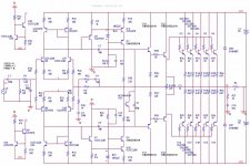
Without having done any calculations, looks reasonable.
Just a couple questions/comments:
1) What is the purpose of the 100 Ohm resistors in series with the bases of the input diffpairs?
2) Same question about the 10 Ohm resistors in series with the bases of Q22/Q23?
3) Are the Miller caps really big enough at only 10 pF?
4) What is the purpose of C6/R42?
5) I would be inclined to go for a longer time constant than 1k / 330 uF for the DC feedback.
6) I can't really read it, but is the cap across the Vbe multipler only 100 pF? I'd be inclined to make it bigger (100 nF at least) if so...
7) The currents in the input diffpairs are biased with a strong negative tempco, so the gain in the input stage will be rather temperature dependent, it will drop at high temp. Probably OK if the enclosure keeps things cool ...
8) Are you planning to include some protection circuitry, to sense overcurrent and / or power supply faults, and reduce output drive, [ or just live dangerously ]
Just a couple questions/comments:
1) What is the purpose of the 100 Ohm resistors in series with the bases of the input diffpairs?
2) Same question about the 10 Ohm resistors in series with the bases of Q22/Q23?
3) Are the Miller caps really big enough at only 10 pF?
4) What is the purpose of C6/R42?
5) I would be inclined to go for a longer time constant than 1k / 330 uF for the DC feedback.
6) I can't really read it, but is the cap across the Vbe multipler only 100 pF? I'd be inclined to make it bigger (100 nF at least) if so...
7) The currents in the input diffpairs are biased with a strong negative tempco, so the gain in the input stage will be rather temperature dependent, it will drop at high temp. Probably OK if the enclosure keeps things cool ...
8) Are you planning to include some protection circuitry, to sense overcurrent and / or power supply faults, and reduce output drive, [ or just live dangerously
]To mirlo
Thanks for your time
1) Saw it on an other amp (Pure and simpel 1 :-/ )
2) Current feedback to the predrivers for stability
3) I'm still working on that, I have simulated it, and the open loop gain and fase of the output is ok. The fase never gets above 90 degrees (Is it here ok to let it go to just under 180 degrees ???)
4) To reduce gain at high freq (still working on the feedback system).
5) Why ? the timeconstant sets the lowerfreq cutoff to about 10 Hz
6) the signal does not go through this cap since the amp isrunning a "positive and negative side"
7)I have the current generator it's in the upper and lower right corner
8) Planning protection...don't know what yet
\Jens
- Status
- This old topic is closed. If you want to reopen this topic, contact a moderator using the "Report Post" button.
- Home
- Amplifiers
- Solid State
- SOS for BJT's in output ???