Something I don't recall ever seeing used in an audio amplifier before, I thought it might provide some inspiration for someone. It's not something that provides any particular benefit for normal use, but may prove useful for constructing high-voltage amps.
Just like parallel output devices can be used to provide higher current, so series output devices can be used for higher voltage. I'm sure I remember there being a proper name for this, but I'll be damned if I can remember what it is. The advantage is that the output devices can be of lower than normal voltage rating. As extra devices are added so the voltage requirements are reduced: With four (twice as many as normal) each one only has half the voltage to deal with. Power dissipation is also spread in the same manner.
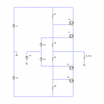
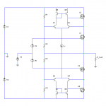
Attached is a schematic showing the simplest possible realization, just to make it easy to see the idea. The inner pair of output transistors is driven as normal. The outer pair is driven to half the output voltage by a simple voltage divider, so voltage across each half of the output stage is shared more or less equally by two devices. There are a number of ways to arrange the output devices by switching around N and P-channel devices, but some arrangements are rather harder to make work than others.
More to follow...
Just like parallel output devices can be used to provide higher current, so series output devices can be used for higher voltage. I'm sure I remember there being a proper name for this, but I'll be damned if I can remember what it is. The advantage is that the output devices can be of lower than normal voltage rating. As extra devices are added so the voltage requirements are reduced: With four (twice as many as normal) each one only has half the voltage to deal with. Power dissipation is also spread in the same manner.
Attached is a schematic showing the simplest possible realization, just to make it easy to see the idea. The inner pair of output transistors is driven as normal. The outer pair is driven to half the output voltage by a simple voltage divider, so voltage across each half of the output stage is shared more or less equally by two devices. There are a number of ways to arrange the output devices by switching around N and P-channel devices, but some arrangements are rather harder to make work than others.
More to follow...
Attachments
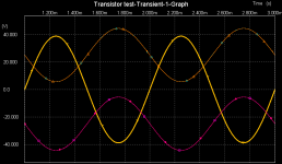
Lastly, here is a graph of the output and voltages across each output device with a 1kHz sine wave input. There are five traces on there but the two pairs of output device voltages overlap precisely. Each device has sees only half the rail-to-rail voltage across it at maximum.
So there you have it. Note that these schematics are for illustrtive purposes only; they are not likely to work perfectly in practice.
So there you have it. Note that these schematics are for illustrtive purposes only; they are not likely to work perfectly in practice.
Attachments
Indeed, I am aware that it is not new, I've seen it in text books before, but as I said, I have not seen it used in an audio amplifier before (phase_accurate has though!), leading me to believe that plenty of people here have probably not considered it before. Thus I hope at least to provoke thought.markp said:That method has been used for years and years.
Lots and lots of amps use this topology, like the old Luxmans, Tigersaurus, to name just two.Mr Evil said:
Indeed, I am aware that it is not new, I've seen it in text books before, but as I said, I have not seen it used in an audio amplifier before (phase_accurate has though!), leading me to believe that plenty of people here have probably not considered it before. Thus I hope at least to provoke thought.
Yes, it does.DigitalJunkie said:I think the Leach "Double Barreled/Superamp" uses a similar setup also.

Ok, ok, I give up! Everyone has learnt of this already!
Don't 'give up ' !
Maybe we can design a new amp using today's parts . In any case one can play around with the design to see if anything can be done to improve it (?).
Guys are trying to work out how the Bryston amps work on another thread. Why not this one ?
Cheers.
don't give up !!
I didn't know it has been used before, but I was considering something like this.
I think it may be great to drive transistors independently
Imagine: these close to output working in class A and these closer to rails swithing on for bigger voltages ??
many ways of improving this I hope
regards
I didn't know it has been used before, but I was considering something like this.
I think it may be great to drive transistors independently
Imagine: these close to output working in class A and these closer to rails swithing on for bigger voltages ??
many ways of improving this I hope
regards
I think there are some "chipamps" that do something like that.
I recall looking over a design with one (I think it was an STK series module.) that would use lower rail voltages for low power output (+/- 35V) up to 50W or something,and then switch to higher voltage rails (+/- 70V) for higher power output,from 50 to 100W.
I think it's "Class-H" or maybe it was "Class-T" I forget..(so many new classifications of amps these days.)
It's not the same as class H (or G, whichever is which). Here there is only one pair of rails, so efficiency remains the same as class B or AB, whereas class G/H is intended to increase efficiency and may or may not include extra pairs of output devices to accomplish the rail switching.DigitalJunkie said:I think there are some "chipamps" that do something like that.
I recall looking over a design with one (I think it was an STK series module.) that would use lower rail voltages for low power output (+/- 35V) up to 50W or something,and then switch to higher voltage rails (+/- 70V) for higher power output,from 50 to 100W.
I think it's "Class-H" or maybe it was "Class-T" I forget..(so many new classifications of amps these days.)
You mean cascoding? It is and it isn't. It seems equally valid to consider the outer transistors as being driven from the base, thus being common collector and not cascode, or driven from the base but with a variable reference voltage, which would be a cascode. I think it would be better not to call it a cascode, since none of the transistors sees a constant Vce.Tensop said:it's cascading isnt it? doesent this cause a larger, and harder to control DC offset ?
It shouldn't have any effect on DC offset, since that is determined only by the two inner transistors the same as normal.
- Status
- This old topic is closed. If you want to reopen this topic, contact a moderator using the "Report Post" button.
- Home
- Amplifiers
- Solid State
- Doubling (or more) output stage voltage capability.