Share my methods to repair/build a discrete power amp
Blowing up the power devices is a one of the most trouble.This thread I post is my experiences to prevent/troublshoot this problem in pratice.Wish you can see what I say(sorry for my poor English) and get the helpful infos
Note: My methods are mainly for the bjt power amp of NFB,but you may apply it (or its parts) for other SS amps(FET amp,pre-amp...etc)
1)Seperate the power devices from the circuit and 'protect' them
This method I use is for the 'big' or complicated trouble(for example,the amp had blew up the power devices)
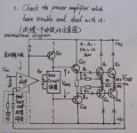
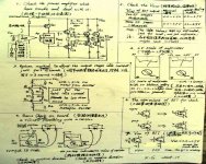
look at the picture below
The pic show the diagram of the bjt power amp of NFB.Q1,Q2 are the power transistors.The key of my method is keeping the NFB active,while disconnect the power transistors.if you don't do that,you can not check correctly the front circuit.
The mothod of keeping the NFB active is soldering two resister(300ohms to 1000ohms,1/4 w or 1/2 w) which between B1 and Vout,B2 and Vout.
After disconnect the power devices and keep the NFB active,you can easily troubleshoot the front circuit,liking a SS pre-amp.
When you finish the troubleshoot of the front circuit,you should confirm the Vbias voltage is not fault before re-connecting the power devices.....if you are still suspicious of the front cicuit,you maybe apply the method below of 5) to continue.
Blowing up the power devices is a one of the most trouble.This thread I post is my experiences to prevent/troublshoot this problem in pratice.Wish you can see what I say(sorry for my poor English) and get the helpful infos
Note: My methods are mainly for the bjt power amp of NFB,but you may apply it (or its parts) for other SS amps(FET amp,pre-amp...etc)
1)Seperate the power devices from the circuit and 'protect' them
This method I use is for the 'big' or complicated trouble(for example,the amp had blew up the power devices)
look at the picture below
The pic show the diagram of the bjt power amp of NFB.Q1,Q2 are the power transistors.The key of my method is keeping the NFB active,while disconnect the power transistors.if you don't do that,you can not check correctly the front circuit.
The mothod of keeping the NFB active is soldering two resister(300ohms to 1000ohms,1/4 w or 1/2 w) which between B1 and Vout,B2 and Vout.
After disconnect the power devices and keep the NFB active,you can easily troubleshoot the front circuit,liking a SS pre-amp.
When you finish the troubleshoot of the front circuit,you should confirm the Vbias voltage is not fault before re-connecting the power devices.....if you are still suspicious of the front cicuit,you maybe apply the method below of 5) to continue.
Attachments
2)troubleshoot the front circuit
the front circuit (dual rail PS) which work have two obvious marks
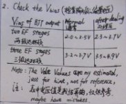
a.the DC voltage of Vbias is below 100MV in general.
b.The Vbias voltage is in the correct range.
The list of the below pic is my estimate of the correct Vbias voltage range,just for hint,not for roference....If your amp trouble on there,the Vias voltage will abviously out of this in general.
I apply the next methods of 3) and 4) to check/troubleshoot the front circuit including input,VAS,drive...etc.
the front circuit (dual rail PS) which work have two obvious marks
a.the DC voltage of Vbias is below 100MV in general.
b.The Vbias voltage is in the correct range.
The list of the below pic is my estimate of the correct Vbias voltage range,just for hint,not for roference....If your amp trouble on there,the Vias voltage will abviously out of this in general.
I apply the next methods of 3) and 4) to check/troubleshoot the front circuit including input,VAS,drive...etc.
Attachments
3)check on-board
This method is in the turn-off state and isn't precision,but can be easily (and safely!) to check the BJTs,Diodes(even resister),then mostly find the bad component.
The tool of check is an analog multimeter(not DMM.I think the people which have much experiences mostly like to use it for troubleshoot in my country).a majority of analog multimeter have 1.5V battery for the Ohm functions(and "high" voltage battery for the max Ohm function),but I would recommend the analog multimeter which have 3V battery for that,because it will show the check-on-board result more clearer and can check the LED,darlington tr,even triac(with another multimeter).
This method maybe a bit complicated....let's go step by step
a.the LV scale of analog multimeter
look at the picture below
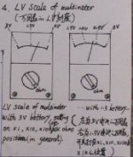
The LV scale indicates the drop-Voltage between the two terminals of check on the Ohm function.(some Chinese analog multimeter have this scale)
Because the LV scale is line.when the multimeter set the Ohm funtion(X1,X10,X100,X1000 in general,I mostly set on X10 in practice) ),the full-scale is 3V(the precision vale is the actual Voltage of inner battery),the indicator at centre show 1.5V....the indicator at start show 0V.
(to be continued)
This method is in the turn-off state and isn't precision,but can be easily (and safely!) to check the BJTs,Diodes(even resister),then mostly find the bad component.
The tool of check is an analog multimeter(not DMM.I think the people which have much experiences mostly like to use it for troubleshoot in my country).a majority of analog multimeter have 1.5V battery for the Ohm functions(and "high" voltage battery for the max Ohm function),but I would recommend the analog multimeter which have 3V battery for that,because it will show the check-on-board result more clearer and can check the LED,darlington tr,even triac(with another multimeter).
This method maybe a bit complicated....let's go step by step
a.the LV scale of analog multimeter
look at the picture below
The LV scale indicates the drop-Voltage between the two terminals of check on the Ohm function.(some Chinese analog multimeter have this scale)
Because the LV scale is line.when the multimeter set the Ohm funtion(X1,X10,X100,X1000 in general,I mostly set on X10 in practice) ),the full-scale is 3V(the precision vale is the actual Voltage of inner battery),the indicator at centre show 1.5V....the indicator at start show 0V.
(to be continued)
Attachments
b.the basic of check on-board
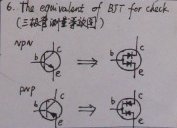
the amp is made of resisters,BJTs,(diodes)....and other components which connected each other.the BJTs in checking state is compound of two diodes.
look at the picture below
the pic whow the equivalent of BJT for check
so,if we know how to check the compound of a diode and a resistor,we can check the transistors(including diodes of course) on-board.
Attachments
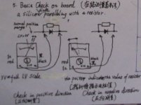
look at the picture below
The pic shows how to check the diode/resistor which connected each other in parallel.set at suit Ohm funtion(X10 in general,but if the resister is small for example a few decades ohms,it should be at X1).when check in positive direction,the LV value of indication is 0.6V-0.7V if the diode is not bad(not short and not disconnect inner),and you can read the resistor value of indication which is non-effective. when check in negative direction,you can read the resistor value of indication(if the diode in not short),and can read the LV value which is useless.
if you set correctly the Ohm funtion and the diode is not bad,the indicator is on the left of the scale when check in positive direction,and on the right of the scale when check in negative direction.so,you can easily justice the diode is good or bad.
because the method isn't precision,you should re-check out-board if you found a bad diode(BJT) on-board....I believe that you had known how to check the devices out-board which method introduced in many books.
I found that we are lucky in my experience,the bad BJT ordinary behaves that: a))the P-N junction is short or disconnect,b))Between the e pin and the C pin are short.
sometimes,the method on-board can not find the trouble BJT(especial be 'soft' bad) and other bad components,then we can go on with the method of 4)
Attachments
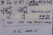
4)check the Vbe of BJT
This method is very simple,but is much helpful.Because the majority BJTs work on line amp area(except for the power BJTs in general and the BJTs in protect circuits ...etc),their Vbe is 0.6V-0.7V.
look at the picture below
If the Vbe of the BJT is higher than 0.7V,the BJT must be dead in general.
If the Vbe of the BJT is lower than 0.6V,maybe the BJT is dead,maybe the other components which relative to it is in trouble. Although it can not tell me the answer, we can trace that to troubleshoot....need to analyse the circuit....")
This method is very simple,but is much helpful.Because the majority BJTs work on line amp area(except for the power BJTs in general and the BJTs in protect circuits ...etc),their Vbe is 0.6V-0.7V.
look at the picture below
If the Vbe of the BJT is higher than 0.7V,the BJT must be dead in general.
If the Vbe of the BJT is lower than 0.6V,maybe the BJT is dead,maybe the other components which relative to it is in trouble. Although it can not tell me the answer, we can trace that to troubleshoot....need to analyse the circuit....
Attachments
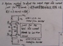
5)adjust the idle current of power stage in safe
look at the picture below
Note:this methods which show in the picture just suit for the idle current is below 200ma
the two resistors are 27ohms to 51 ohms,2 watt(1w as well,but don't work continue in a long time),they can 'protect' the power BJTs.I often use 47 ohms 1W.
look at the picture below
Note:this methods which show in the picture just suit for the idle current is below 200ma
the two resistors are 27ohms to 51 ohms,2 watt(1w as well,but don't work continue in a long time),they can 'protect' the power BJTs.I often use 47 ohms 1W.
Attachments
The thread of Chinese verion which I posted last month is on here
http://www.hifidiy.net/dispbbs.asp?BoardID=2&replyID=42514&id=5000&star=1&skin=0
This is the link of the whole picture including the 7 pictures above
I repaired the marantz PM-6 integrated amp in succeed two months ago,using my methods.
Those are the dead components I found and desolded.I found dead resistors just by their appearance
(the end)
Good luck and enjoy in DIY audio
X.G.
http://www.hifidiy.net/dispbbs.asp?BoardID=2&replyID=42514&id=5000&star=1&skin=0
This is the link of the whole picture including the 7 pictures above
An externally hosted image should be here but it was not working when we last tested it.
I repaired the marantz PM-6 integrated amp in succeed two months ago,using my methods.
An externally hosted image should be here but it was not working when we last tested it.
An externally hosted image should be here but it was not working when we last tested it.
Those are the dead components I found and desolded.I found dead resistors just by their appearance
An externally hosted image should be here but it was not working when we last tested it.
(the end)
Good luck and enjoy in DIY audio
X.G.
XG this is a perfect DIY text... in acordance with the philosophy
And i am happy to read all your informs, in a good English, at least, i ensure you that is better than mine.
hehe..i also make my confusions with "each,wich,with,wish".... sounds the same to me...so.... i go writting the same too (What a damn ignorance mine, isnt'it?)
I thank you, the method used to "load" the amplifier, making a "virtual presence" of the output transistors, when they are not in place was very clever....my deep congratulations.
A very good Job you done to some of us....a lot of guys will use your method, despite many will feel ashamed to say they did not even notice that possibilities.
But you contribute to me, and as i have many young friends to teach electronics, in poor guys schools....in a matter of one year, more than 500 will use your method "XG troubleshooting method"
Many people already discovered those things, but they are worst than you in one special aspect....they close their mouthes....without help other guys. And this makes the difference.....What a difference this made!
XG, now Xiang to me, i am happy to say that you can use a little big pictures if you want it.
Our limit size is 800 by 600 pixels and we can go maximum 100K each picture.
And the images you done, some were unreadable, this way, if we feel confused we cannot check image to make our own brain troubleshooting.
I tried to expand....i could not, as resolution was not so good to expand.
I expand one, at least this one i could, and i distorted some, as that expansion will not destruct the meaning of the numbers and letters, i really do not know if this changes the meaning of your simbols....maybe they took another meaning.
Please, don't go, stay longer and contribute with us.....many chinese avoid to post as language is some trouble, and sometimes people forget to say thanks....but they certainly read those good things alike you post.
There are many with only basic knowledge, and there are some "Gods" here too..... they honored us with their intervenction and presence sometimes.
Mr Pass, John Curl, Graham Maynard, Hugh Dean, Pierre lacombe, Eva and many others.....maybe they are around 50 special knowledge man here... and more than thousand very skilled guys are here too.
But there are the young boys here, needing those informs...they will not thank you always.... some of them will turn nervous when you teach basic things.... they feel offended....but those are feel and do not create big troubles to the ones that have real good intentions.
You, and many, as representative of ancient cultures, in my point of view, are a gift to us.
regards,
Carlos
XG. one streched and deformed image, expanded near the limit.
This one was streched for 750 to 600.... we can not go further....the size is 800 by 600 maximum...... i tried 801 by 600 and resulted negative.
My culture, always trying to have a little more freedom....that's our problem, we have already too much, and finding more.
regards,
Carlos
This one was streched for 750 to 600.... we can not go further....the size is 800 by 600 maximum...... i tried 801 by 600 and resulted negative.
My culture, always trying to have a little more freedom....that's our problem, we have already too much, and finding more.
regards,
Carlos
Attachments
Hmm, maybe this limit is still valid for JPGs ?
I shortly attached GIF with 939*631...
http://www.diyaudio.com/forums/showthread.php?postid=530572#post530572
To X.G. !
Clever way to trace down the bug in a defect amp !
Mike
I shortly attached GIF with 939*631...
http://www.diyaudio.com/forums/showthread.php?postid=530572#post530572
To X.G. !
Clever way to trace down the bug in a defect amp !
Mike
Rigth MikeB, your image goes in excess pixels, but with low memory used too.
This forum is really well made.... some calculations are done....as you use less space in kilobytes, no problem to be a little over the limit.
Also the avatar have some tolerance too...75 X 75 pixels results in 5625 pixels..... if you use one picture with 40 by 80,.... it enters too, as the result of the multiplication 40 X 80 results in 3200....beeing economic..... sometimes we can jump over the "filter".
regards,
Carlos
Re: XG. one streched and deformed image, expanded near the limit.
Sorry,I made a mistake on here( my Chinese post don't have it).Now correct it:
the full-scale is 0V(after the 'ZERO' Ohm calibrated) ,the indicator at centre show 1.5V....the indicator at start show 3V(the precision vale is the actual Voltage of inner battery).
Thank your commend,Carlos
I will re-take a photo clearer and post here.
X.G. said:
3)check on-board
a.the LV scale of analog multimeter
the full-scale is 3V(the precision vale is the actual Voltage of inner battery),the indicator at centre show 1.5V....the indicator at start show 0V.
Sorry,I made a mistake on here( my Chinese post don't have it).Now correct it:
the full-scale is 0V(after the 'ZERO' Ohm calibrated) ,the indicator at centre show 1.5V....the indicator at start show 3V(the precision vale is the actual Voltage of inner battery).
destroyer X said:This one was streched for 750 to 600.... we can not go further....the size is 800 by 600 maximum...... i tried 801 by 600 and resulted negative.
My culture, always trying to have a little more freedom....that's our problem, we have already too much, and finding more.
regards,
Carlos
Thank your commend,Carlos
I will re-take a photo clearer and post here.
X.G. said:The thread of Chinese verion which I posted last month is on here
http://www.hifidiy.net/dispbbs.asp?BoardID=2&replyID=42514&id=5000&star=1&skin=0
This is the link of the whole picture including the 7 pictures above
An externally hosted image should be here but it was not working when we last tested it.
I upload this picture (gif 1654X1200
)now.Attachments
- Status
- This old topic is closed. If you want to reopen this topic, contact a moderator using the "Report Post" button.
- Home
- Amplifiers
- Solid State
- Share my methods to repair/build a discrete power amp