Mr Evil said:.."Proper" biasing for class B means that each transistor is conducting for exactly half the cycle...
Hi,
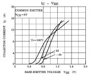
The picture below shows the transfer characteristic IC-VBE of a frequently-used transistor 2SC5200. What is, in your opinion, the "proper" VBE value for class B biasing? What is the expected IC current in this case?
Regards,
Milan
Attachments
Class-A can sound good without NFB, even if the room does get too hot to listen in.
The problem is not especially related to output device voltage bias.
As MikeB says, it is down to design, and the relevent design point is minimising propagation delay whilst maintaining high NFB bandwidth to ensure low non class-A output stage distortion when the load is reactive.
Cheers ............ Graham.
i think if u need a medium to high power amp then the best choice will be class AB .
I think high power class a amps dissipate too much power in the output transistors that make them less linear , there wont be no crossover distortion but i think the linearity is worse ,unless u will use 100 pairs of output trannies so they will remain in room temp.
With todays output transistors its very easy to bias class ab output stage and to get very low crossover distortion , thats why i think AB is the best choice .
Certainly there is some leeway in the definitions, but it is helpful to distinguish between the normal class AB where there is a significant region where both transistors conduct, and the optimum class B where the two transistors are as close to 180 degree conduction each as possible.maylar said:That's a sticky point with some engineers. In most classic definitions, Class C is defined as "Significantly less than 180 degrees" and only applies to tuned RF circuits...
I know of no way to calculate what the optimum bias is. The only way is to make distortion measurements as the bias is adjusted. As bias is increased from zero distortion will fall, then at some point it will begin to increase again. The optimum is where distortion is at a minimum of course. In my experience this can be anywhere from as little as 0.5mA up to a more AB 20mA, depending on the devices used.moamps said:
Hi,
The picture below shows the transfer characteristic IC-VBE of a frequently-used transistor 2SC5200. What is, in your opinion, the "proper" VBE value for class B biasing? What is the expected IC current in this case?
Regards,
Milan
The problem is ensuring that the bias remains correct under all conditions. If it falls too low then distortion will rise considerably. It increases by a smaller amount if bias is too high, which is why class AB is popular I suppose.
I found some Phillips Systems, using class D, very nice sounding equipment.
But, this do not show me too much, as inside some system you can compensate here or there, if bad bass you improve speaker displacement....if too much treble distortion they reduce power and divide in many twetters to have some sound pressure without going to distortion.... matched boom boxes can be, sometimes, interesting.
I was very well impressed with one Phillips model..... wide world top model with shaking meters and routating lamps.... a christmas tree making sound.
I said do myself....aaaagh!..... this is an illusion, this can be good...and them i check all others...Panasonics.... Sony, Aiwa, all them... the three class D models beat them all in quality.
I will buy to check in my home.... to research that "thing"....sometimes we delay a lot to evaluate... and diferences sometimes are only some equalization with better voice reproduction.... 1 to 4 kilohertz increase make wonderfull results.... also cutting the damn 250 hertz that is awfull!...those tricks confuse a lot.... to compare must be flat..... and they are not flat!
Hello guys, can you tell me something more,, related class D, not only that is PWM....i am asking a real deep explanation, a detailed explanation please.
That "thing" had not weigth..... seems empty!!!...hehe...no transformer....switching power supply and a fan making a good job....the power was very good.... something alike 150 watts each channel...i cannot understand...the consumption is 120 Watts.
I AM CONFUSED!...HELP!!!!
Carlos
Class B.
If you want to know about why Class B *might* work well, you have to read what Doug Self has written about it.
He had a website up with fairly complete info - as series of articles in EW+W (the Brit mag).
He advocates Class B over AB.
His main thrust is that he can get a closer to "flat" gain through the crossover region with Class B than with AB... at least that is how I recall reading his stuff some time back.
Personally, I suspect that he never really listens to much, and if he does, I suspect that he's not terribly sensitive to the same "compromises" that I am... just speculating here, his amps might sound peachy keen.
There are a number of amps, including some by Erno Borbely that are set up with biasing into Class A or AB according to your pleasure that you can try both ways. Either way you have a fairly large capability in terms of output current, and number of paralleled devices, and a very nicely done drive circuit, usually DC coupled without servos. That's one way to make some comparisons. I suspect you'd be hard pressed to hear much of any difference with his amps biased either way - assuming an appropriately large PS section (no dipping and jiving).
_-_-bear
Hi,
D. Self designed his "blameless" power amp as a classAB topology.
During his discourse he accepted that he found his blameless ran much lower bias than was considered conventional by other designers and concluded that maybe you could liken it to a classB topology. But he did NOT claim it as a classB amp.
In addition he also designed a "trimodal" power amp that was switchable between classAB and classA, summer and winter settings.
By the way for a design insight, D Self's articles are excellent, just a pity he uses current mirror on LTP and Cdom (miller compensation) as I suggest that these two items may well be what ruins the sound of an otherwise good amplifier.
regards Andrew T.
sss said:
With todays output transistors its very easy to bias class ab output stage and to get very low crossover distortion , thats why i think AB is the best choice .
Yes, i think you really made the point !
Regarding the fact, that the AKSA is rated to be one of the best amps,
it shows that ClassAB is good choice...
Mike
AndrewT said:Hi,
D. Self designed his "blameless" power amp as a classAB topology.
During his discourse he accepted that he found his blameless ran much lower bias than was considered conventional by other designers and concluded that maybe you could liken it to a classB topology. But he did NOT claim it as a classB amp.
In addition he also designed a "trimodal" power amp that was switchable between classAB and classA, summer and winter settings.
By the way for a design insight, D Self's articles are excellent, just a pity he uses current mirror on LTP and Cdom (miller compensation) as I suggest that these two items may well be what ruins the sound of an otherwise good amplifier.
regards Andrew T.
Excellent summation Andrew.
I have heard the Trimodal, a Silicon Chip Class A amp and the JLH 1996 version.
The later is vastly superior imho. Self never was much of a challenge for the late JL Hood when it came to debating the virtues of the best sounding amplifier design in the feedback columns of WWW.
macka
Mine AKSAs, as i have 8 boards, half from hugh, half Aska (the opposite and fake)
Fake, because i make them at home...hehe...awfull, bigger, and loose some brigth in the top end reproduction...too long copper rails sometimes cause problems creating capacitances between those rails and "dragging" or "sucking" hi frequencies.
I have four with 200mA bias, this way, i have some power inside class A, as my supply is 42 Volts...there's 8.2 watts in stand by mode...if you accept that 20 percent can be a good "Class A" possibility, i can have 1.5 watts of pure class A each channel.... at nigth i do not use more than that, as i have family sleeping and neigthboors too.
It is the best amplifier in my mind, had compared with friends, and was judge with care... and Hugh Dean amplifier was the winner....i was out of the judgement. i made the work of instalation to prepare the test and made the modifications my friends asked...they do not like Hugh, as they could have not the schematics, as Hugh do not like to publish some details that "makes de difference" and they asked those details and i did not told them...so...they had subjective reasons to try to create some problems to Aksa amplifier under test.
I made a blind test...no one knows when Aksa was playing or not...i confused them the most i could...but conditions where fair...same speaker, same position, same signal, same power, same air pressure..... Aksa was the winner.
Fourty years researching to find one that real can be appreciated for anyone...now Hugo is called different, they hate Hugh.... Hu cu.... that have some meaning over here....but not easy to understand, even for my people.
It kicked JLH A--, and JLH are wonderfull amplifiers.... was a big shame!.... i was so surprised that i check connections 4 times!...to have sure, the winner was not JLH!..... other that produced better sound than JLH was the Graham Maynard circuit, and this one remember the JLH, some cousin i suppose...or at least a JLH based and improved design.
I am talking in BJTs amplifiers, cannot talk about FETs as i heard once and did not like, and i did not compare with tubes, but i think a good tube design will be better than all BJTs designs.
A good idea is to find someone that have on Aksa, and go with your amplifier with you....compare and tell me!...hehe....may be very frustrating man. Aksa will smash your amplifier alike one elefant passing over an ant.
That class D impressed me very well.....and i perceive power, as speaker was hard to move with fingers and it jumped out of the box, giving me the idea that some amperes where flowing inside....cannot be those PMPO that multiplies by 10 or 20 or 30 the maximum distorted signal, measured with a short time burst, two channels added to make a number bigger and result multiplied by 30....that Phillips were producing at least 50 watts each channel and the consumption was 120 Watts!.... this do not make sense.....too low consumption!!!...can be more efficiency or class D designs?.... HEY!... Tell me something, please, about those class D amplifiers.
regards,
Carlos
"Aksa will smash your amplifier alike one elefant passing over an ant."
I don't think so, otherwise the AKSA will smash commercial one like
supernova on bazilla...
ClassD, As outputdevices only know two states, ON & OFF, no heat
is dissipated in them. Only switchingtime creates some losses, and
internal resistances.
So the output from ClassD is a pulsewidemodulated squarewavesignal,
and then "converted" to an analog signal with filters.
Mike
My God!...MikeB, i am ashamed to like that "thing"
Those convertions have some ratio, some sampling, and never is the same as analogic source.
But can be good, as we like CD recordings... very feel CD recordings but there are some that satisfies me.
One music from Dire Straits, that iniciate with some guitar "talking" are wonderfull in sonics. A guitar heavily distorted making a conversation.
Thank you Mike, now i have a better idea related those amplifiers... by the way mike, to you know the Class D efficiency.... watts heat versus watts audio.
regards,
Carlos
The theroretical efficiency of class-d is 100%. In practice it is between 85 % and 95 %.
The switching frequency is considerably higher than the sampling rate of the CD !!! and ordinary PWM amps can be regatrded as analog and they do therefore have an infinite resolution level-wise (this is of course theoretical).
I am still convinced that 90 % of today's audio applications could be using class-d amps. The other 10 % are very critical and/or very high-end applications or people that simply dislike the working principle of class-d.
And though I am a fan of class-d I won't blame anyone who doesn't like it at all.
Regards
Charles
Hi Charles,
I agree with you. In this increasingly energy-conscious world, Class A is arguably already in the undertakers chapel, and Class AB will eventually be supplanted by Class D.
However, analog design is always improving. A fruitful research area, just now becoming commonplace, is error feedforward. This could well extend the useful life of Class AB amps, as they are at least 50% efficient. This is not wonderful, but much better than Class A.
Mike, your comment about current mirrors is very true. A current mirror by its very design forces imbalance into a long tailed pair. This is because of the bias current needed by the VAS, which is driven from one arm, not the other. The Cdom is also a big sonic influence, as you point out, but if the cap type is right and its value exactly correct, the sonics are little damaged.
Switching rates of digital amps are on the rise. They started around 600KHz and now some are up to 2MHz. I understand that 2.5MHz gives 20 bit resolution for the audio pass band. Increasing the switch rate reduces the sonic influence of the output filter, too, and this is perceived to be a major influence on sound quality with such amplifiers.
The primary benefits of Class D are the high efficiency and the absence of heatsinks. Heatsinks are a huge expense with conventional analog design.
Cheers,
Hugh
Hi Hugh,
Class-A to class-D is a greater jump than I can envisage due to the always necessary output filtering placing reactive components between an output stage and a high frequency driver. I could see class-D becoming acceptable for high power full range driver applications, but ongoing difficulties remaining for realistic reproduction at frequencies where DVD-A, SACD and Blue Ray are taking us; frequencies where amplifiers like your own are already competent anyway!!!
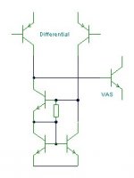
There is nothing to worry about when mirroring a differential stage - if - the three transistor arrangement is used. A perfect dc balance can be set up where the VAS bias current is matched by the third transistor (base plus base-emitter resistor) current. The resistor is likely to be between 4k7 and 10k in value, and the arrangement minimises distortion, offset error also output impedance. As attached;-
However, if a VAS connected C.dom is used with any differential plus mirrored stage then C.dom charging sets up a cyclic dynamic output shift wrt input, which does not show up in THD measurements, but which many people do hear. Where the C.dom acts against a resistor, and is not so high in value as to reduce open loop gain at audio frequencies, then it can control the NFB driven potential for correction overdrive and ensure overall stability. Does simulation or test gear reveal a superior specification when the reproduced sound is at its best? No, because the two do not naturally go together; minimising measured THD degrades loudspeaker reproduction !!!
Am I right Hugh in suggesting that you could vastly reduce the measured THD of your amplifier, but in doing so you would make it sound worse ?
Cheers .......... Graham.
Class-A to class-D is a greater jump than I can envisage due to the always necessary output filtering placing reactive components between an output stage and a high frequency driver. I could see class-D becoming acceptable for high power full range driver applications, but ongoing difficulties remaining for realistic reproduction at frequencies where DVD-A, SACD and Blue Ray are taking us; frequencies where amplifiers like your own are already competent anyway!!!
There is nothing to worry about when mirroring a differential stage - if - the three transistor arrangement is used. A perfect dc balance can be set up where the VAS bias current is matched by the third transistor (base plus base-emitter resistor) current. The resistor is likely to be between 4k7 and 10k in value, and the arrangement minimises distortion, offset error also output impedance. As attached;-
However, if a VAS connected C.dom is used with any differential plus mirrored stage then C.dom charging sets up a cyclic dynamic output shift wrt input, which does not show up in THD measurements, but which many people do hear. Where the C.dom acts against a resistor, and is not so high in value as to reduce open loop gain at audio frequencies, then it can control the NFB driven potential for correction overdrive and ensure overall stability. Does simulation or test gear reveal a superior specification when the reproduced sound is at its best? No, because the two do not naturally go together; minimising measured THD degrades loudspeaker reproduction !!!
Am I right Hugh in suggesting that you could vastly reduce the measured THD of your amplifier, but in doing so you would make it sound worse ?
Cheers .......... Graham.
Attachments
- Status
- This old topic is closed. If you want to reopen this topic, contact a moderator using the "Report Post" button.
- Home
- Amplifiers
- Solid State
- Classes of operation vs. sound quality