Actually the RA970BX isn't dc coupled ! It has the original coupling cap in place. The 1.1 V dc offset appears to slowly ( after 30 minutes or so ) drop down to around 70 mV like it is on the other channel. While checking voltages I noticed the two errors in the circuit diagram. Something else is wrong here. This amp was 'modified' by the original owner. Even installed and external IEC power socket ! Can't say if it's an earlier problem coming back again ! I don't know what else they did or could have done. The input opamp on the diagram is AD827. On the board its AD826. The tone opamp should be NJM 2114 but it's AD827 ! Both are on DIP sockets . So they were changed after they added the DIP sockets. I saw the base collector short also ! That's too obvious as a mistake !Since all this is double checked wonder how the errors got through.
The RA01 was new when I got it.
The RA01 was new when I got it.
Last edited:
Made and tested the protection board. Appears to work well by itself. Triggers at more than +/- 0.7 volts dc.
I had added the LED as an indicator when the relay trips under fault condition. However I over looked the fact that from the same line dc goes to the LED indicator and the 12 V trigger line on the rear panel. These draw current through the LED causing it to light up even without fault conditions. It now just indicates the circuit is powered up !I didn't want to change anything.
I did some rudimentary tests on the amp. Response is flat up to 20 Khz and drops down to about -0.3dB at 10 Hz.
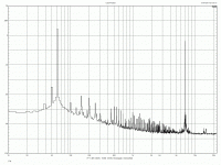
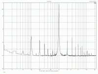
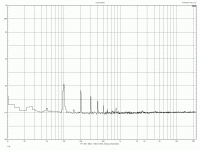
Distortion with the tone control switched on is much higher ( as seen on the FFT ) and this is clearly audible when you listen to it ( without using any bass or treble boost or cut ). I had the top cover off and the laptop was running on the mains supply. Both responsible for some low level trash on the FFT.
I'll do the test again carefully so that I can compare it with the FFT after the input stage is filtered. Will check the plan I have, to try and minimise any track cuts or drilling.
I managed to attach the protection board without cutting any tracks. Removed a jumper and soldered the wires to those points. It's late now and I am going to bed. I'll take some pictures tomorrow.
Tests on the stock amp
I did a FFT on the amp at about 2V into 4 ohms and for the IMD test using 60Hz and 7Khz mixed 4:1 ratio. There is one with just the noise floor where the lap top was on batteries and the generator shut off ( not disconnected ).
I think the power supply noise might go down with a filter on the power supply line. Still figuring out how to fix the cap multiplier to the board with minimal track cutting and to use some of the copper leads to hold the board up by itself. That would reduce lead length and not require any fixtures to hold the board.
While the protection circuit works well on it's own, there is a problem after installation. There are some other dc currents flowing through the board that shouldn't be there. I need to fix that. It drops the available voltage to the trip circuit.
Attachments
Been looking at the performance increase with a simple RC filter and a capacitance multiplier. Theoretically the cap multiplier has a much better PSRR on simulation (!) . But I wonder if that increase will be audible ! It means an additional active device which sometimes could do weird things if not installed properly. The RC however seems a safe bet with a slight loss of output voltage on clipping which shouldn't really matter at all. Cap multiplier loss is more !
I'll just try the standard diode, resistor and capacitor configuration. I see many people watching what's going on but no one has said anything about schemes they have tried. After this test I'm going to close up the amp. If I try the cap multiplier it will be very much later on. No time right now. I'm also closing up my RA970BX amp. It's an older design and the board looks 'old'. No time to meddle with it now. But I still have to iron out the issue with the protection board on the RA01. I think it shouldn't be too hard to do that. Will have to relocate the power points I think.
I'll just try the standard diode, resistor and capacitor configuration. I see many people watching what's going on but no one has said anything about schemes they have tried. After this test I'm going to close up the amp. If I try the cap multiplier it will be very much later on. No time right now. I'm also closing up my RA970BX amp. It's an older design and the board looks 'old'. No time to meddle with it now. But I still have to iron out the issue with the protection board on the RA01. I think it shouldn't be too hard to do that. Will have to relocate the power points I think.
The protection circuit is wrong ( post 33). Two transistors and the diode are not required ( D2/Q4/Q5/R2). I don't know what I was thinking at the time. Maybe had a whiff of grass from the neighbors house !
Anyway after correction it works fine. It wasn't to do with the protection itself but severe loss of voltage to the delay /relay circuit. Anyway that's solved. I wasn't too keen to make changes without the protection installed. A fuse is not good enough.
After studying the manual carefully for a long time I've determined where to cut the tracks ( two ) and where to locate the filter ( Diode/R/C ). I'll do it tomorrow. In the meantime I want to keep listening to selected tracks so that after the change I can listen to the same ones to see if they are different.
Unfortunately can't do an A/B . Comparing against the other stock channel is possible but not quite the right thing to do. It would however drastically reduce changeover time ! I could do that too...just in case !
I've been listening to the dc coupled RA-01 and feel the ( direct coupling ) mod was worth it. The RC filtering of the input stage is pending. However after listening to several discs tonight I feel I should listen to it some more before trying any other changes. As it is, it sounds much cleaner and is tighter in the bass than it used to be.
Will compare it with some other amps I have here to see where it stands currently. After that I'll try out the RC filter mod. Not very happy about having to cut tracks ! Will study this further before doing something so drastic. If there is a messy way around it but avoids track cuts ( just for experimentation ) I'll do that. Then of course if it makes a significant difference I'll cut the tracks !
Will compare it with some other amps I have here to see where it stands currently. After that I'll try out the RC filter mod. Not very happy about having to cut tracks ! Will study this further before doing something so drastic. If there is a messy way around it but avoids track cuts ( just for experimentation ) I'll do that. Then of course if it makes a significant difference I'll cut the tracks !
Comparisons with other amps
Currently I am comparing the dc coupled RA-01 with a Creek 5350 .
There are differences . But overall the Creek is better.
The Creek has a deeper bass end which is also very much under control. Nice tight bass. The RA-01 doesn't seem to extend that low ( though the frequency response doesn't show anything wrong !) and certainly doesn't sound as 'tight' !
Maybe I should use the word powerful and punchy for the Creek sound.
Mids on the RA-01 is the place which needs refinement. It's not as smooth as the Creek. However at the HF end the RA-01 seems to be more defined.Sounds are more separated such that quick percussion sounds far more accurate. Very high HF comes our very well, better than the Creek. Like tinkling sounds especially at low levels. Low level sounds at the background are more audible on the Creek. We are listening to an opamp and the power amp in the RA-01. The RA-01 uses an OPA2604 . I can bypass that and see how the power amp fares.Bias on the Rotel is low. Set according to the manual at 4 mV across0.22 ohms . That is only 18 mA !
However I must admit that the levels were not controlled at all. Tests were done at night. Today I'll set them up accurately ( within 0.1 dB ) . Level differences can exaggerate the differences we hear ! However for it's price the RA-01 is certainly a good unit. I'm not sure that the supply filter will make a significant difference but since everything is ready , I'll test that after the current listening tests.
The three things that could be tried are:
1. The supply line filters for the input stage
2. The removal of the electrolytic decoupling cap in the NFB stage. That could lead to dc offset problems. But with the dc protection in place it isn't a worry for me. Don't know if it will lead to offset that is too much to correct . However this cap could be critical wrt the sound quality !
3. Removal of the OPA 2604 'preamp' stage.
Just a quick note. I got some time today to make some changes. I tried the RA-01 without the OPA2604. Big drop in gain obviously. So it's only the power amp section working with dc coupling !
Later I removed the NFB coupling cap. As expected the offset went up. The offset was about -240mV and -180 mV. But that's safe on the speaker and it doesn't trigger the protection circuit which needs over +/- 0.6 V to trip the relay.
I like what I hear , thought it isn't perfect . Transients have that nice clean edge and low level sounds are very well reproduced. I think I'll keep this amp !
Will do more tests on the weekend and explain the differences in sound. No time to do that now.
Hi. Anyone mod a rotel ra-04 SE amp.There are 3 caps in the signal line from imput 10uf 100uf and 10uf into the amp. can i lower the uf and to what. thanks. I have changed the psu caps 2 nichion and 14 resistors plus some wire and have to say it sounds better than my pioneer a-400. Resistors are vishay and shinkoh. Any help would be great. Thanks
- Status
- This old topic is closed. If you want to reopen this topic, contact a moderator using the "Report Post" button.
- Home
- Amplifiers
- Solid State
- Simple upgrade for Rotel RA-01 amp..


