Hi Guys
Out comes another lurker! I have recently finished a set of Leach amps and thought this post a few pics that may provide some inspiration to others as others posts have done for me. Brian GT is one contributer I remember well - but there were many many others. The B/W pics were done by one of my buddies - Moo - Thx Moo
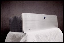
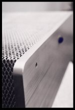
Have we lost our marbles? - well no - we have in fact found them. Have a look at the power switches on the front. I did not like any of the switches that I was able to get here in South Africa so I decided to Macgyver one. I hope this gives a few of you guys some ideas, I have thought of using them for volume knobs as well as selector switches. I have special Audiophile versions of these marbles for sale at only $900 US each - Each expertly machined by dwarves follwed up with a generous sprinkling of the famous "Fairy Dust"")
I am absolutely ecstatic with the way this amp sounds - way better than alot of the commercial amps I have heard. I can best describe it as quite smooth & neutral. I have mainly been exposed to "mid-fi" Rotel - Nad - Marantz etc. As a huge generalisation I will say these can "sound loud" at high volume levels - I dont get this from the Leach - even though my neighbours think otherwise .
I have read alot about the reported lack of bass. My opinion is that the Leach amp provides a very natural 'detailed' bass if that makes any sense. It probably wouldn't to me unless I had actaully heard it for myself - NB it is not for everybody.
I found it very interesting that the amount of noise out of this amp with no input source was disturbingly low. I would have to place my ear within +- 5cm or 2.5Inches from the speakers to be able to hear anything, as compared to the NAD integrated that I owned where I could hear hiss from half way across the room.
Thank you Prof Leach for giving this design to the Diy Audio community - your contribution is greatly appreciated.
I will be following up with a website with a couple more pics & details as soon as I get done with the project I have on @ work . I will show you how to get slave labour working for your DIYAudio project
Keep building dudes!!!
Out comes another lurker! I have recently finished a set of Leach amps and thought this post a few pics that may provide some inspiration to others as others posts have done for me. Brian GT is one contributer I remember well - but there were many many others. The B/W pics were done by one of my buddies - Moo - Thx Moo
Have we lost our marbles? - well no - we have in fact found them. Have a look at the power switches on the front. I did not like any of the switches that I was able to get here in South Africa so I decided to Macgyver one. I hope this gives a few of you guys some ideas, I have thought of using them for volume knobs as well as selector switches. I have special Audiophile versions of these marbles for sale at only $900 US each - Each expertly machined by dwarves follwed up with a generous sprinkling of the famous "Fairy Dust"
I am absolutely ecstatic with the way this amp sounds - way better than alot of the commercial amps I have heard. I can best describe it as quite smooth & neutral. I have mainly been exposed to "mid-fi" Rotel - Nad - Marantz etc. As a huge generalisation I will say these can "sound loud" at high volume levels - I dont get this from the Leach - even though my neighbours think otherwise
.I have read alot about the reported lack of bass. My opinion is that the Leach amp provides a very natural 'detailed' bass if that makes any sense. It probably wouldn't to me unless I had actaully heard it for myself - NB it is not for everybody.
I found it very interesting that the amount of noise out of this amp with no input source was disturbingly low. I would have to place my ear within +- 5cm or 2.5Inches from the speakers to be able to hear anything, as compared to the NAD integrated that I owned where I could hear hiss from half way across the room.
Thank you Prof Leach for giving this design to the Diy Audio community - your contribution is greatly appreciated.
I will be following up with a website with a couple more pics & details as soon as I get done with the project I have on @ work
. I will show you how to get slave labour working for your DIYAudio project Keep building dudes!!!
Attachments
And Another
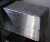
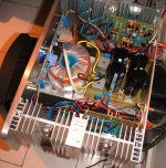
And finaly - the insides
This is the second build of the amp - the first looked terrible without the Power supply PCB. I also created a PCB for the Clipping indicators (As per Leach's circuit) & power lamp. This PCB also holds the push switch.
The toroid is a 700VA (the largest that coule be manufactured localy) unit yielding 60 Volts DC under load.
Power output on the amp was measured with a scope as 128 into 8 & 242 into 4 with no sign of clipping.
Attachments
Hi,
What is that extra block of alloy attached to the heatsink above the transistor? diodes?
Did you have to rotate the transformer to minmimise hum? or did it work in first position?
I am impressed with the doubling of power into 4R. Is this one channel driven? Can you test with both channels driven?
Have you increased any of the time constants to help the bass response? details please.
regards Andrew T.
You are correct Andrew - that is with one channel driven - at the time I didn't have enough power resistors to measure both channels, and my buddy who owns the scope has now moved to another province so I no longer have access to it. I would imagine that the value will be significantly lower with both channels driven in this way as the transformer is unlikely to provide the necessary current. I will say though that I have driven a pair of 4 ohm floorstanders with good results.
The extra blocks are certainly for the biasing diodes, and I didnt attempt to position the transformer in any special way - It simply didn't introduce any nasties first time off. They are of quite high build quality - and filled with resin to minimise hum. To my ears they are virtually hum free - Some of the other EI transformers I have tried were terrible in this regard
The amp was built stock standard with nearly all parts as per the Leach spec - including the silvered mica caps. IE I did nothing to improve the bass (although I have read that biasing it higher can give more "thump" - I am more of a construction man that an amplifier design expert & prefer to leave those decisions to people that know more than me
If possible try to use CNC milling bits. They are normally 1/2 Inch shank & have 6 cutting edges.
I wanted to use a template to do the rounding on the corners and these milling bits are not available with guide bearings so I couldn't use these. I used an ordinary 2 flute 1/2 inch shank straight cut bit with bearing guide. I would insist that the bit is TCT and that it is of the highest possible quality. The reason for this is that the cutting edges can experience quite a bit of shock during cutting and if the cutting inserts are not properly bonded to the bit you could end up with a nasty high speed projectile being flung at your nether regions. Use some lubrication like wd-40 or Q-20 on the piece to stop the bit ftom heating up & getting blunt. By peice I mean the Aluminium
In my view this is not enough in terms of safety - even high quality bits can shatter - so wear lots of body armour. I borrowed a full face mask and also strapped 22mm MDF panels to most of my body. Rather safe than sorry!
The router should be industrial (mine is a triton +-2400Watts) as otherwise the possibility of biting can be increased as there is not enough torque). I ran it @ about 8000RPM & took small cuts. I noticed no degradation / chipping on my bit.
For all out there reading thinking of attempting this - please - please BE CAREFULL. Make sure you know how to use your router PROPERLY as you can be KILLED by these things.
Given all the doom gloom and warnings - the whole operation didn't go badly at all and I will definately be doing more of this work.
I wanted to use a template to do the rounding on the corners and these milling bits are not available with guide bearings so I couldn't use these. I used an ordinary 2 flute 1/2 inch shank straight cut bit with bearing guide. I would insist that the bit is TCT and that it is of the highest possible quality. The reason for this is that the cutting edges can experience quite a bit of shock during cutting and if the cutting inserts are not properly bonded to the bit you could end up with a nasty high speed projectile being flung at your nether regions. Use some lubrication like wd-40 or Q-20 on the piece to stop the bit ftom heating up & getting blunt.
By peice I mean the Aluminium In my view this is not enough in terms of safety - even high quality bits can shatter - so wear lots of body armour. I borrowed a full face mask and also strapped 22mm MDF panels to most of my body. Rather safe than sorry!
The router should be industrial (mine is a triton +-2400Watts) as otherwise the possibility of biting can be increased as there is not enough torque). I ran it @ about 8000RPM & took small cuts. I noticed no degradation / chipping on my bit.
For all out there reading thinking of attempting this - please - please BE CAREFULL. Make sure you know how to use your router PROPERLY as you can be KILLED by these things.
Given all the doom gloom and warnings - the whole operation didn't go badly at all and I will definately be doing more of this work.
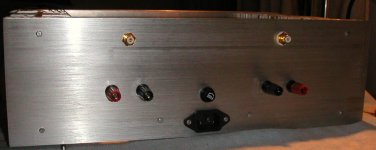
Nice work on the aluminum front panel and the overall
chassis design. My Ultimate Leach Amplifier should look
this good if I ever get around to building it. Especially
impressed you did this with a wood router.
If my bother-in-law and I were on speaking terms and
didn't live on opposite sides of the continent, I'd be using
his Bridgeport vertical mill to do machining work. Or I
might speak to a friend of his who lives here who has
similar equipment.
I'm currently testing Brian Bell's PCB which uses plastic
case transistors and will use either his or Jen Rasmussen's
layout for my next version. It eliminates a small rat's nest
of wiring and keeps circuit paths very short. I'd like to have
a complete amplifier channel neatly mounted on a single
heatsink, which is why I'm leaning towards Jen's layout.
And yes, it's pretty quiet. My major source of noise may be a
small ground loop; hiss is nearly inaudible and Brian's board
looks even quieter.
OK - finally the pics are up in HQ. see http://byrd.fotopic.net/
Hey Damon - Thx. You - like me - are also a man with the time contraints. I will say that wiring is the nastiest bit of building this amp, however in terms of the T03P packages are you not worried about heat transfer?. If you / anybody else anybody out there has tried running the leach @ high power into 4R for extended periods with the T03P configuration I would like to hear, as I am also interested in getting away from the T03 packages - They limits you in terms of heatsinking as well
I got those heatsinks from a small dingy electronics shop here in Durban - They are quite close to those that Prof Leach specifies - but are about 1.5 cm shorter (height wise). I epoxied 2 of these heatsinks together to make 1 whole side. From what I remember I only paid about R60 per piece (Ie R120 per side) for them. Alot better than the +-R400 ($66US) each I was quoted from RS Components
Nice to see some other ZA guys around here - Ladysmith - Must be a hard life - I guess there are not too many electronics supply stores around there Send us a mail if you want further details, I forget the name of the shop atm but whould have the reciepts somewhere.
Hey Damon - Thx. You - like me - are also a man with the time contraints. I will say that wiring is the nastiest bit of building this amp, however in terms of the T03P packages are you not worried about heat transfer?. If you / anybody else anybody out there has tried running the leach @ high power into 4R for extended periods with the T03P configuration I would like to hear, as I am also interested in getting away from the T03 packages - They limits you in terms of heatsinking as well
I got those heatsinks from a small dingy electronics shop here in Durban - They are quite close to those that Prof Leach specifies - but are about 1.5 cm shorter (height wise). I epoxied 2 of these heatsinks together to make 1 whole side. From what I remember I only paid about R60 per piece (Ie R120 per side) for them. Alot better than the +-R400 ($66US) each I was quoted from RS Components
Nice to see some other ZA guys around here - Ladysmith - Must be a hard life - I guess there are not too many electronics supply stores around there
Send us a mail if you want further details, I forget the name of the shop atm but whould have the reciepts somewhere.The plastic cased transistors ought to be robust enough,
provided the heatsinks are sufficiently sized and well-ventilated.
I'd sort of prefer to run three pairs, especially if rail voltages
were a little higher, but I haven't had any problems with
overheating to date. When the amplifier is working properly,
it's thermally stable.
It's a tradeoff between robustness and a clean physical
design; a commercial amplifier maybe should go with the metal
case transistors for the extra margin of safety.
Since I have a supply of spare outputs, I may attempt to
test Brian's board to thermal failure, assuming I don't burn
up the transformer. I'll definitely have to put a fan on my
test load. I can get 225 watts out of it as is, into a low-impedance load, at the risk of baking my power transformers
with sustained testing.
I have more than one project on indefinite hold for lack of
suitable enclosure, or means to build one. I have a
forced convection heatsink assembly for TO-3 metal transistors
that's prewired for up to five output pairs on two channels;
it's sat in my collection for 20 years waiting to do something
with it. I think I could easily get 500 watts/channel with that
thing, provided I had the transformers. Hopefully next year
I can get started on that project, at least to demonstration
level (demonstrating how many output transistors I can blow
up with 90 volt rails).
provided the heatsinks are sufficiently sized and well-ventilated.
I'd sort of prefer to run three pairs, especially if rail voltages
were a little higher, but I haven't had any problems with
overheating to date. When the amplifier is working properly,
it's thermally stable.
It's a tradeoff between robustness and a clean physical
design; a commercial amplifier maybe should go with the metal
case transistors for the extra margin of safety.
Since I have a supply of spare outputs, I may attempt to
test Brian's board to thermal failure, assuming I don't burn
up the transformer. I'll definitely have to put a fan on my
test load. I can get 225 watts out of it as is, into a low-impedance load, at the risk of baking my power transformers
with sustained testing.
I have more than one project on indefinite hold for lack of
suitable enclosure, or means to build one.
I have aforced convection heatsink assembly for TO-3 metal transistors
that's prewired for up to five output pairs on two channels;
it's sat in my collection for 20 years waiting to do something
with it. I think I could easily get 500 watts/channel with that
thing, provided I had the transformers. Hopefully next year
I can get started on that project, at least to demonstration
level (demonstrating how many output transistors I can blow
up with 90 volt rails).
- Status
- This old topic is closed. If you want to reopen this topic, contact a moderator using the "Report Post" button.
- Home
- Amplifiers
- Solid State
- Another Leach Amp - Have we lost our Marbles?