When I read about theories of output stages, they say that classB (and AB) power amp suffers a "Crossover distortion". With my limited knowledge, I accept it as happening when NPN and PNP output stages will be 1=on and the other =off. The transition between on and off causing this crossover distortion.
I assume this happens because each transistor will be off and on. If we can make all transistor never off (like classA), maybe this crossover distortion will dissappear. (Is this right?)
I'm looking for a way to always have both transistor on. Someone said there is a patent on "never turning off" in class (A)B, but I couldn't find it. Does anyone know where it is?
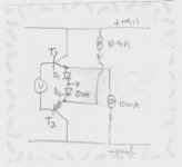
I think about this drawing that I attached. This is complementary EF output stage. If I put D1 and D2 after emitors, before output, and put 10mA CCS to rails, this way both T1 and T2 will never turn off, minimum will always have to pass 10mA in every condition.
I have question about this idea.
1. T1 and T2 will never turn off. But can this idea eliminate crossover distortion in class(A)B amp?
2. But it makes the D1 and D2 conducting/not conducting. Does diodes in this mode gives another kind of on/off distortion? If it gives "diode distortion" that is worse than "transistor distortion" then this idea is not good.
3. If this idea is working, what kind of diode is suitable for D1 and D2? Ordinary diode/Schottky/Fast recovery/Soft recovery?
I assume this happens because each transistor will be off and on. If we can make all transistor never off (like classA), maybe this crossover distortion will dissappear. (Is this right?)
I'm looking for a way to always have both transistor on. Someone said there is a patent on "never turning off" in class (A)B, but I couldn't find it. Does anyone know where it is?
I think about this drawing that I attached. This is complementary EF output stage. If I put D1 and D2 after emitors, before output, and put 10mA CCS to rails, this way both T1 and T2 will never turn off, minimum will always have to pass 10mA in every condition.
I have question about this idea.
1. T1 and T2 will never turn off. But can this idea eliminate crossover distortion in class(A)B amp?
2. But it makes the D1 and D2 conducting/not conducting. Does diodes in this mode gives another kind of on/off distortion? If it gives "diode distortion" that is worse than "transistor distortion" then this idea is not good.
3. If this idea is working, what kind of diode is suitable for D1 and D2? Ordinary diode/Schottky/Fast recovery/Soft recovery?
Attachments
lumanauw said:
I'm looking for a way to always have both transistor on. Someone said there is a patent on "never turning off" in class (A)B, but I couldn't find it. Does anyone know where it is?
http://www.diyaudio.com/forums/showthread.php?postid=282339#post282339
S.Tanaka, "New Biasing Circuit for Class B Operation," JAES, 1981, Vol. 29, No 3, p. 148 (patented)
Nelson Pass: patent # 3,995,228
Steven
Hi, Steven,
Thanks for the link. You also think the same too (but for classA?)
Thanks for the link. You also think the same too (but for classA?)
Do you have a small JPG on this patent?Nelson Pass: patent # 3,995,228
I have done similar experiments and I got real nasty crossover distortion => not a good ideaEva said:Diode reverse recovery and turn-on delay, by themselves, are much worse than crossover distortion. Schottky diodes may be an interesting option


Thanks for the input.=> not a good idea
I see passdiy and passlab website, but couldn't find patents by Mr.Pass.
Where can I see all his audio patents?
Threshold series amps are marvelous in this area. Many kind of amp, with different cct, but same purpose. NP incorporated EC like cct, but he says its not for EC. Now I know what they was intended. To eliminate Xover distortion.
lumanauw said:Hi, Steven,
Thanks for the link. You also think the same too (but for classA?)
Do you have a small JPG on this patent?
Type the patent number in here: http://patft.uspto.gov/netahtml/srchnum.htm
or look here: http://l2.espacenet.com/espacenet/viewer?PN=US3995228&CY=gb&LG=en&DB=EPD
Steven
What is so-called class AA?
http://www.diyaudio.com/forums/showthread.php?s=&threadid=45690
http://www.diyaudio.com/forums/showthread.php?s=&threadid=23590&highlight=
It's kind of other thing, but very smart. It's based on Sano Hirota patent. NP made the same function, but different cct patent.
Waw, after re-looking at Threshold 400A-4000 schematic, it really incorporate an "all transistor non-switchoff" cct.
But I don't understand this Statis2-3 schematic. There are 2pcs of 4K7 R attached to the output at VBE multiplier.
I try to route it with many ways, but I still cannot relate this 2 R's for "non switchoff" function.
1. What is this 4k7R for?
2. In Statis2-3, the output stage still turn off, not like threshold 400A-4000?
Attachments
Maybe I am missing something in Lum's post. Xover distortion doesn't come from the xstrs turning off and on, it comes from their doing so at the wrong times. In class AB both side are on at the same time, and you may or may not get Xover dist depending on the adjustments.
Assume a sine wave.
In a plain old vanilla power stage, the signal hits the bases of the output xstrs. On the pos side, the signal rises until it gets to the turn on voltage of the pos output xstr. Then the output signal starts to rise with the input. SInce the Output xstr has that half a volt base potential to overcome, the first half volt of the input signal rise does not come out of the amp. The same thing happens on the neg side. SO if we just connected the bases of the two sides together and fed them the signal we would have our input sine come out the amp as a sine wave with a small flat space at every zero crossing representing that lost half a volt to each side. Crossover distortion.
In practice we add circuitry to bias the output xstrs right to the brink of conduction. Now any tiny bit of signal will be enough to cross the threshold and turn the output device on. That way we get the full sine wave in the output.
So if each output needs a half volt bias on it, I expect about one volt between those bases overall. The bias adjust on the amp is essentially setting this amount. Too little bias and the xover notch appears. Too much bias and both sides are on at once, fighting each other and excess current flows. Just right is just right.
THat is a 101 simplification of xover distortion. Or are you talking about someting else?
- Status
- This old topic is closed. If you want to reopen this topic, contact a moderator using the "Report Post" button.
- Home
- Amplifiers
- Solid State
- Crossover distortion