http://whaan.homestead.com/files/page5.html
I don't like capacitors. They are often the most expensive parts in an amplifier circuit. This is why I'm attracted by this circuit. As I searched through the forum, I saw someone once mentioned that the simulation result of this cuicuit is good. So I simulated this circuit with pspice, but what I see is severe crossover distortion at the output.
I used mpsa42/92 and j200/k1529 in place of the transistors in the circuit diagram. Is this going to be a problem?
"I don't like capacitors. They are often the most expensive parts in an amplifier circuit. This is why I'm attracted by this circuit. "
You will need a minimum of about 3,300µF per rail and per channel for good 8R performance, double this if driving 4R. Also note that the amp shown has additional bypass caps, from the size they look like about 33µF and 0.47µF .
"I used mpsa42/92 and j200/k1529 in place of the transistors in the circuit diagram. Is this going to be a problem?"
Well I wouldn't build it with those parts. Use something like the MPS A06/A56 for the input pairs. You will probably have a problem making it work with the J200/K1529 pair, they are D-MOS and the original J160/K1058 are S-MOS. In general D-MOS are for switching and have a vertical construction with very touchy temperature characteristics for linear use. The S-MOS are for audio and have a lateral construction and very predictable temperature performance. The quick way to tell the difference is to see what is connected to the case, if the drain is its D-MOS, if the source is its S-MOS. Magnetec, Xicon, and Semelab also make the types you need. One pair of BUZ900/905 would make a 50~100W amp, depending upon bias and heatsinking.
http://www.magnatec-uk.co.uk/latmos_pricing.shtml
That amp will also need an input resistor to ground for a bias leakage path. If the input pot went open the output would latch up, use a 100K. You may want to hook a capacitor across the bases of the driver pair, it will allow the drivers to go into class AB if the FETs need more drive current at high frequency.
Hi EJ,
I've been playing a lot with this circuit last year. I have made some comments and questions about the circuit that time so maybe you have seen my post. I
I really liked the circuit as it was quite simple, easy to understand and simulated just perfect... a little too perfect.. my guess was that the MOSFETS I used in my simulator were modelled as perfect symmetrical devices ... does that make sence?..
I used class A biasing since I thought the cicruit does not have very much gain to reduce cross-over distortion with feedback. I also made a complete IRF510/IRF9510 version for headphone use which simulated also very good (post is some where on this forum).
Finally I chose the JLH 10Watt Class A there was more info on the web for it (excelent site from Grey I think? or GRollings?)..
Go for it .. simulate extensively to get a feel for the tricky biasing... there is a itterative method for that you could try with a simulator.
Goodluck,
Thijs
I like the builder's clinical description of the amplifier:
So now I need an amplifier that likes music? Sheesh!
Nice job on the amp, though. I like the thermometer decal.
Amplifier sound is in a way friendly, polite and clean. It never gets on your nerve and it likes music.
...
This gives you the feeling that it really understands the music or the performer who plays.
So now I need an amplifier that likes music? Sheesh!
Nice job on the amp, though. I like the thermometer decal.
Dear all,
I am the newbe in diy amp. I have also spot this circuit and already d/l the circuit. However, I have wondered on how to figure out the power supply circuit. Could someone told me why there is totally four rectifier install in the circuit. How they are connected in the circuit?
Thank you for the kind assistance.
Attachments
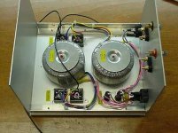
The amp uses two totally separated power supplies. One rectifier for each winding, then the two DC sources are connected in series creating positive and negative voltage and ground in the middle. The smoothing caps are at the main board.
The power supply is very convential.
The power supply is very convential.
sam9
The confusion is that the PS module apears to provide four pairs of rails. A closer look, if my eyes don't decieve shows that bridges are pairs of half wave recifiers. Each pair the equivalent of a single full wave bridge rectifier. As you say the circuit is nothing special. The physical implementation is not seen every day.
The advantage of this arrangement that comes to mind is that this is a very high power amp and the arrangement keeps the actual current far below the rating of the bridges and also facilitates heat dissapation from the bridges.
I live in Taiwan, so I'm afraid my answer might not help you too much. However, you can send a mail to limin_wu@diyzone.net in English. This guy also lives in Taiwan, and owns the largest audio DIY commercial website here. I think he will be glad to help you.
- Status
- This old topic is closed. If you want to reopen this topic, contact a moderator using the "Report Post" button.
- Home
- Amplifiers
- Solid State
- Has anyone ever built this MJAMP??