Do you think I would post a thread if I found it on Google? 
Obviusly they aren't for FREEE! It's a 30 years old amp! What the hell! and a nothing special amp! Why they can't distribute them for free?
Someone has scanned (don't know if it is the exact term) them?
I need them, but I won't pay for a 30 years old mediocre amp schematic.
The Marantz' are for free, and they are VERY good: why I have to pay for a Sansui?
I don't know how much difference there is, but the A80's here:
http://schforfree.seedhost.com/archive/?path=Audio/products/amplifiers-integrated
http://schforfree.seedhost.com/archive/?path=Audio/products/amplifiers-integrated
Thank You! It might be useful.
I just turned it on: I don't have the control panel, it has been lost so I don't know what the knobs and the switches are for. I tweaked them a bit and the output power indicator started to move, but no sound (and yes, I've checked the wiring!).
I think I have to change the output transistors, but I've found a burned resistor near the headphone jack: maybe it's cutting the signal to the speaker? who knows....
Again, if anyone has the right schematic I will be grateful. If you don't want to post it, you can email them to me...
You could try asking here:
http://www.sansui.us/BBS_General/wwwboard.shtml
http://www.sansui.us/BBS_General/wwwboard.shtml
Sansui A40
I too do hav Sansui A 40. It came to me completely dead. It seemd so many epople tried their hand on it b 4 it came to me. I re did it.
The output transistors were 2SA798 n the complementry 2SC18.. You cn try finding it in google for the correct conmplementry. You can also use MJE2955T/MJE3055T. Which Ima using on my amp
The Resistor at the Headphone jack is 220 Ohms 1/2 watt.
You have my support and total agreement Giaime, why to pay to old unit schematic
I also think that people could keep last model in secret to avoid other factories to copy...but i cannot understand why to keep old models in secret... when the industry is already closed... we can understand they are not giving support anymore.
This would be free to us, information that would come together the manual, the operation manual and the schematic could come together...more honest and decent.... or you will buy a black box... we do not know what have inside...if fine electronics or a chip amplifier with a small transformer.... the one that wish more detailed informations could buy the service manual using mail... but schematic and operations instructions should come together the equipment, inside the box.... many companies worked this way during seventies and eigthies...when internet started to run...communications very fast..they decide to close themselves to inform us "what goes inside"... afraid of the competition.
I have searched too, and i could not find also the model you need.
I still think that is not decent to sell you a black box with no informations about what goes inside.... unless small factories were you can contact the President, Manager, Designer.... alike many we know in our forum...those are exception.... you have informations what goes inside in advance.... this makes part of the agreement if double supply or single supply and all that stuff.
No me piace molto la denominazzione, mediocre amp...grumpf!...grrrrr!....but i can agree a little with you.... let's say... average performance unit... medíocre in my country means different than average... means weak, bad, less than average..ma va benne..siamo tutti buonna gente...vá benne signore.
regards,
Carlos
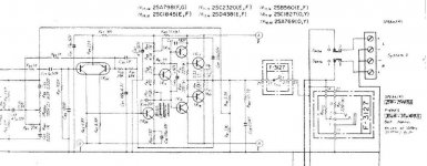
linuxguru said:Thanks - the image seems to be a bit blurry, however.
For the life of me, I cannot understand the feedback network consisting of R53 (?) (39k) , R55 (68k), C17 (100u/6.3v), C33 (?) (1 pF), R19 (?) (1k) , around LTP TR05. Probably some missing components?
That network provides DC feedback, not AC feedback. That big electrolytic to ground filters out the AC component. This is necessary so the amplifier can steer its quiescent DC operating point.
AC feedback is sent through the Baxandall tone control network. I've seen this scheme in a few old designs. It keeps the input bias current from flowing through the tone control pots, so the amplifier won't suffer a fit of when a pot wiper starts to wear.
Cheers,
Glen
> AC feedback is sent through the Baxandall tone control network.
OK, I spotted that loop - starting with the resistive divider with R79 (3.3k) / R41 (?) 330R connected to the output. So this is probably the active variant of the Baxendall network, with the transfer function of the Baxendall being part of the feedback network. That's going to be impossible to analyse without the rest of the schematic, in particular the Bass control of the Baxendall and the take-off point for the input to the LTP.
OK, I spotted that loop - starting with the resistive divider with R79 (3.3k) / R41 (?) 330R connected to the output. So this is probably the active variant of the Baxendall network, with the transfer function of the Baxendall being part of the feedback network. That's going to be impossible to analyse without the rest of the schematic, in particular the Bass control of the Baxendall and the take-off point for the input to the LTP.
- Status
- This old topic is closed. If you want to reopen this topic, contact a moderator using the "Report Post" button.
- Home
- Amplifiers
- Solid State
- Schematics needed for a Sansui A-40