Hi!
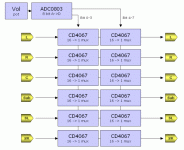
Based on Nelson Pass design, gets to me the idea of using the CD4067 MUX to create a 6 way volume control.
As I have a lot of ADC's and MUX's, I want to make something with them.
I attach the block diagram of it.
The ONLY question is if it's a good idea to put 4 bits to each 4067 an I can have a 32 level volume control.
Ops... another:
The values of the series resistores are...
Is there a way to calculate them in a 2dB or 3dB step?
I've searched a lot and didn't find anything.
Thanks in advance for any answer.
Attachments
audioPT said:....gets to me the idea of using the CD4067 MUX to create a 6 way volume control....
Hi,
This can be nice project. Don't give up.
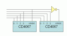
(I have an idea about using 5 control bits (two 4067 with inhibit) and 32 steps with any attenuation step accuracy.)
Regards,
Milan
")
audioPT said:Hi!
Based on Nelson Pass design, gets to me the idea of using the CD4067 MUX to create a 6 way volume control.
As I have a lot of ADC's and MUX's, I want to make something with them.
I attach the block diagram of it.
The ONLY question is if it's a good idea to put 4 bits to each 4067 an I can have a 32 level volume control.
Ops... another:
The values of the series resistores are...
Is there a way to calculate them in a 2dB or 3dB step?
I've searched a lot and didn't find anything.
Thanks in advance for any answer.
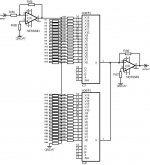
It works properly. I made volume controll with this solution. The only thing is that 4067 needs high impedance load to work with low distortion. So You have to use some impedance buffer between the first, and the second 4067. You have to take care with the DC on the input. It will cause switching noise, so use coupling capacitor!
My friend use this volume controll with valves. Nice unit!
sajti
audioPT said:Any help to find resistor values? [/B]
STEP=2dB, Ratt=47kohm
Rn(kohm):
R1= 5,693
R2= 6,084
R3= 6,114
R4= 5,721
R5= 4,985
R6= 4,098
R7= 3,240
R8= 2,507
R9= 1,924
R10= 1,475
R11= 1,134
R12= 0,875
R13= 0,678
R14= 0,528
R15= 0,412
R16= 0,323
R17= 0,254
R18= 0,200
R19= 0,158
R20= 0,124
R21= 0,098
R22= 0,078
R23= 0,062
R24= 0,049
R25= 0,039
R26= 0,031
R27= 0,024
R28= 0,019
R29= 0,015
R30= 0,012
R31= 0,010
R69= 0,037
R64,65,66=47k
R67,68=27kohm
R32-63=47kohm
Attachments
What about a DAC08 ?
So what would you say if you would input the signal on the reference voltage of a DAC for example DAC08 ?
Of course, this reference voltage will be the ground voltage ( actually both Vref+ & Vref-).
Input cap necessary.
The rest is identical to a tipycal DAC08 schematic.
????
So what would you say if you would input the signal on the reference voltage of a DAC for example DAC08 ?
Of course, this reference voltage will be the ground voltage ( actually both Vref+ & Vref-).
Input cap necessary.
The rest is identical to a tipycal DAC08 schematic.
????
- Status
- This old topic is closed. If you want to reopen this topic, contact a moderator using the "Report Post" button.
- Home
- Amplifiers
- Solid State
- ADC + 4067 Volume Control