Walt Jung has long been an advocate of 2 op amp (or op amp + buffer) composite circuits and points out their advantages – check his web site; “Op amp Audio” series
Gerald Graeme has also advocated 2 op amp composite amplifier, with high loop gain from 2 pole responses – “Amplifier Applications of Op Amps” 1999 devotes a chapter to composite op amp circuits and their compensation
This sim circuit topology is close to circuits I have built and I have verified that they can achieve measured 1KHz harmonic distortion (and 1KHz IMD from 1:1 10KHz + 11KHz) below my 160dB instrumentation limit
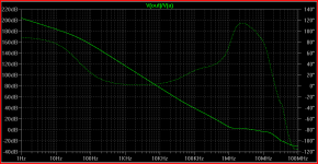
Composite amplifiers can reduce active device contributions to audio frequency distortion to unmeasurable levels (1 V input, 20 KHz sim results: )
The output op amp is a modified integrator that provides large audio frequency gain, those in the know will object that the loop phase response, which exceeds 180 degrees around 100 KHz invites oscillation or poor recovery from clipping
(the Loop Gain Probe is available from the LtSpice Yahoo group files area - just cut it out and delete .prams lines if you don't want to use it)
The clipping response is greatly improved by the symmetrical clamping diode bridge that holds the input op amp to +/- 1 V output when the output op amp saturates, this means that the input op amp is held in its linear operating region, its contribution to loop gain and phase shift is minimized, and its output only has to slew ~ 1V to when recovering from saturation ((1.6 V @ 20 KHz input, V(n005) is Lt1022 output)
Simple back-to-back diodes would also provide for the improved clipping response, but the bridge reduces diode capacitance and nonlinear conduction current that add directly to the feedback error voltage and cause nonlinear distortion
(distortion and phase margin # may be off slightly, I plotted those with all 1N418 diodes before it occurred to me to reduce clamp voltage with Schottkys, this means diode feedthru may be slightly higher due to higher capacitance form lower reverse bias on D1,2)
Gerald Graeme has also advocated 2 op amp composite amplifier, with high loop gain from 2 pole responses – “Amplifier Applications of Op Amps” 1999 devotes a chapter to composite op amp circuits and their compensation
This sim circuit topology is close to circuits I have built and I have verified that they can achieve measured 1KHz harmonic distortion (and 1KHz IMD from 1:1 10KHz + 11KHz) below my 160dB instrumentation limit
Composite amplifiers can reduce active device contributions to audio frequency distortion to unmeasurable levels (1 V input, 20 KHz sim results: )
The output op amp is a modified integrator that provides large audio frequency gain, those in the know will object that the loop phase response, which exceeds 180 degrees around 100 KHz invites oscillation or poor recovery from clipping
(the Loop Gain Probe is available from the LtSpice Yahoo group files area - just cut it out and delete .prams lines if you don't want to use it)
The clipping response is greatly improved by the symmetrical clamping diode bridge that holds the input op amp to +/- 1 V output when the output op amp saturates, this means that the input op amp is held in its linear operating region, its contribution to loop gain and phase shift is minimized, and its output only has to slew ~ 1V to when recovering from saturation ((1.6 V @ 20 KHz input, V(n005) is Lt1022 output)
Simple back-to-back diodes would also provide for the improved clipping response, but the bridge reduces diode capacitance and nonlinear conduction current that add directly to the feedback error voltage and cause nonlinear distortion
(distortion and phase margin # may be off slightly, I plotted those with all 1N418 diodes before it occurred to me to reduce clamp voltage with Schottkys, this means diode feedthru may be slightly higher due to higher capacitance form lower reverse bias on D1,2)
Attachments
I thought I might collect some of these multiloop/gain boosted composite op amp ideas, this thread is already here...
jcx said:Floating supply op amps may be modeled with some of the “multiple pole-zero” models that TI and Analog devices have presented in their app notes
But they don’t use them uniformly or often, many Boyle style macromodels are still being released
So you have to look inside the model to tell – Spice node 0 should not appear inside a op amp model
Once you start digging in you realize how poor many models are and you might just roll you own with 1-2 poles and a output resistance to generically play with bootstrapping
Here I point out some of the problems I had with the author of the AD8610 op amp model:
http://www.diyaudio.com/forums/showthread.php?s=&threadid=13590&perpage=10&highlight=&pagenumber=2
The OPA227 model seems to get gain right – I‘ve not tested whether output current appears plausibly in the ps terminals – yet another layer of modeling accuracy
I have been playing for several years with power supply bootstrapped op amp circuits
One previously known composite op amp with power supply bootstrapping showing loop gain enhancement from the bootstrapping of the internal voltage gain stage is from Mohapatra and Sandman’ 1980 GB patent
The sim shows Mohapatra&Sandman’s topology with the OPA227 model, I call this a feedforward bootstrap topology
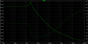
The loop gain is substantially boosted by the bootstrap connection when the load impedance Rload is high
Because the OPA227 is in series with the bootstrap amp there is no improvement in its output impedance so you can see the gain boost disappears with heavier loading
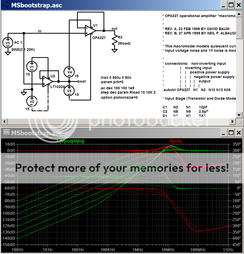
The “loop error” I’ve plotted (in green) is essentially the inverse of the loop gain – at 10 KHz with the high load impedance you can see 100 dB loop gain => 1 GHz “GBW”
Attachments
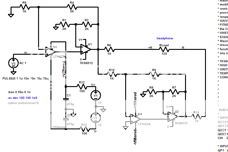
Rod Elliott used to have an article at his site with a headphone amp consisting of a VFB + CFB combo. It was never a build project, but something he did to try out some samples of CFB ADSL drivers he had got. Unfortunately, that article seems not to be around anymore, and he now uses only the CFB amps as they are. Anyway, as far as I remember, his idea with the combo was to get the precision of VFB combined with the speed of CFB, and he said then it was the best headphone amp he had heard. I don't remember the details, whether there was any local feedback around each op amp, for instance.
jcx said:(the Loop Gain Probe is available from the LtSpice Yahoo group files area - just cut it out and delete .prams lines if you don't want to use it)
Hi jcx,
I'd like to use the Loop Gain Probe. I downloaded it from
the LtSpice yahoo group. Using your circuit, I set .param prb=-1
and ran it. No errors in the transient analysis with .asc and .asy
files in their proper place.
I then did an AC analysis run and I can get a plot of Vout in
magnitude and phase. it looks flat out to ~300Khz.
How do I tell LtSpice to show a plot of loop gain in magnitude
and phase?
Thanks,
Mike
the loop gain probe uses both V and I sources to test return difference which gives the correct result anywhere in the feedback loop - the usual simplified test with just a V source works best when the impedances are mismatched by the largest amount possible so that information/energy transfer is well approximated as flowing in one direction only
to use the loop gain probe you have to run 2 analysis, as in the commented out .step in the example above, then the correct value for the loop transmission (Bode's T commonly (and sometimes approximately) "return difference", “return ratio”, “loop gain”, ”excess gain”, “feedback factor”) is given by the complicated expression at the top of the sheet, you have to copy that into the plot as the trace definition you want to display (clik on the expression, copy its text, then go to plot>add trace and paste the expression at bottom of the box)
I don't know where all of the Spice syntax for that expression is documented - the @1, @2 suffixes refer to the trace "steps" - the multiple passes of sim caused by the .step command
Loop Gain probe theory:
http://www.thekunderts.net/ken/docs/c&d2001-01.pdf
https://www.eecs.berkeley.edu/~boser/courses/240_2004_sp/lectures/L09 lecture.pdf
middlebrook paper:
http://www2.enel.ucalgary.ca/People/Haslett/Jwhgrad.htm
jcx said:...is given by the complicated expression at the top of the sheet, you have to copy that into the plot as the trace definition you want to display (clik on the expression, copy its text, then go to plot>add trace and paste the expression at bottom of the box)
Hi,
I cut and pasted the expression:
1/(1-1/(2*(I(V
 :i)@1*V(p:x)@2-V(p:x)@1*I(V:i)@2)+V(p:x)@1+I(V:i)@2))
(note:
is actually the text chars colon followed by p)and LtSpice complains about unknown current requested: I(V
:i)so I found a .plt file that had this expression:
1/(1-1/(2*(I(Xp:Vi)@1*V(Xp:x)@2-V(Xp:x)@1*I(Xp:Vi)@2)+V(Xp:x)@1+I(Xp:Vi)@2))
and I cut and pasted this expression and was able to get
it to work. It duplicated your results.
Looks like the names used in the loop probe changed or something.
Thanks for the help,
Mike
Black's Error Feedforward is a Composite amp too - is sub ppm good enough?
I grabbed Bob's example sim from the TPC/TMC debate in the Cordell Book thread http://www.diyaudio.com/forums/soli...lls-power-amplifier-book-119.html#post2413197
my poking at it seems to indicate that the distortion is limited by the slow output Q and simply can't be made much better by feedback - especially the THD 20KHz that Bob likes as a simple quality metric (at least without going deep into conditional stability territory with 3-rd order or higher loop gain schemes)
if you can't fix up a amp with more feedback then the other tool is Black's Error Feedforward - rare in audio because of the difficulties power output combiner but famous none the less due to Quad’s "Current Dumping" amplifier
a error feedforward amp is defined by having 2 independent power amp paths to control the output - and the consequent difficulty of combining the outputs without their mutual loading causing unwanted additional (destabilizing) feedback
The VanderKooy Lipshitz Error Feedforward paper http://quad405.com/jaes.pdf shows several schemes - "Current Dumping" actually wraps negative feedback around the "dumper" amp stage - but 2 other schemes are shown - I chose the Parallel Feedforward from their fig 4b - which doesn't intentionally add loop feedback to the main amp and the coupling through the output impedances of the amps is minimal when used with a frequency selective power combiner
so the following is a Composite Amp using a large, slow discrete amp and a fast error feedforward op amp path
the instrumentation op amp measures the error at the diff pair input of the main amp with a gain of 10x, and then the CFA DSL driver op amp integrator provides the required error correction V drive for the Resistive leg of the L,R power output combiner network
Bob's THD 20KHz number is improved by ~20x in this sim
you will need Bob's zip file and to put my asc in the same folder with Bob's Cordell Models.txt file or you can download Bob's transistor models from his
book's site
Attachments
Last edited:
One previously known composite op amp with power supply bootstrapping showing loop gain enhancement from the bootstrapping of the internal voltage gain stage is from Mohapatra and Sandman 1980 GB patent.
JCX, can you give more details on this patent? I wasn't able to finde it. Thanks!
Samuel
the Search is weak in this one master..
"interface circuits" on 1st page of google search Google Mohapatra and Sandman’ 1980 GB patent
clik: Full Text at United Kingdom Intellectual Property Office (IPO)
Espacenet - Bibliographic data
"interface circuits" on 1st page of google search Google Mohapatra and Sandman’ 1980 GB patent
clik: Full Text at United Kingdom Intellectual Property Office (IPO)
Espacenet - Bibliographic data
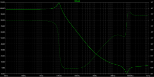
you mean something with a loop gain curve as complicated as this?
the "upper bode step" comes from the 2-pole T network feedforward around a slower level shift stage interaction with the combining network to drive the output Q
the point-to-point prototype built with slower parts shows good agreement with its sim, but isn't as tightly "tuned" as the sim the plot below comes from - time to start re-learning Eagle...
rh poles, zeros, aren't usually "desired" parts of a design - but may be consequences of other choices with desired benefits – sometimes you just have to work with them for the other benefits - think of designing around them as "learning opportunities"
Attachments
Last edited:
I found rh pole useful to add intensionally in some cases (unlike rh zero), which most texbooks either omit or say one doesn't want it, because it's bad without thorough analysis. OK, they mension Nyquist plot going twice around the point of interest...
For the global loop it is all you dream about , -6db/dec rolloff with positive 90deg phase shift, which sound like a cigarette that cures cancer, but the rest of loop must also have enough gain to push the rh pole to lh in closed loop. This is very tricky and hard to stabilize under any condition, but can do wonders once working...
Enough said, still under my work, for 5 years now, first implemented without analysis, sort of 'everybody knows something can't be done, until ...' story.
I am posting the link up to something I have played with recently
Augmented Feedback Error Correction (AFEC)
I like your clamp circuit jcx - I will need to try it in the next few days.
Augmented Feedback Error Correction (AFEC)
I like your clamp circuit jcx - I will need to try it in the next few days.
- Status
- This old topic is closed. If you want to reopen this topic, contact a moderator using the "Report Post" button.
- Home
- Amplifiers
- Solid State
- High loop Gain Composite Op Amp Circuits