Just a quick post to start off because it's late here. I've been having a few thoughts about crossover distortion and emitter follower output stages versus common emitter types. EF ones are voltage output i.e. low impedance whereas CE ones are current output - high impedance. The point is though, the two emitters or two collectors are effectively in parallel during the time both transistors are conducting, but only one of those arrangements really works properly when paralleled.
That's enough of a clue for now. Here's the topology I am going to play with. I'ts an inside-out version of a CE power stage that is fed by what amounts to a common-mode choke so the power supply doesn't have to flap up and dowm with the audio signal, and so it can supply more tham one amplifier channel. More later.
Uhhh.... I seem to have erased the schematic. Will redraw and post it tomorrow.
That's enough of a clue for now. Here's the topology I am going to play with. I'ts an inside-out version of a CE power stage that is fed by what amounts to a common-mode choke so the power supply doesn't have to flap up and dowm with the audio signal, and so it can supply more tham one amplifier channel. More later.
Uhhh.... I seem to have erased the schematic.
Will redraw and post it tomorrow.The problem with xover "distortion" is that as the devices are being turned off the gain becomes non-linear. So, the two devices, one being turned ON more and one being turned OFF more do not sum flat.
Suggest checking out Doug Self's website and articles, he's got a very good and complete treatment of this issue...
_-_-bear
Suggest checking out Doug Self's website and articles, he's got a very good and complete treatment of this issue...
_-_-bear
Not in a hurry
OK. So it's taken me almost 5 years to get this thread going again...
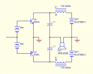
Quoting myself from above --> emitter follower output stages are voltage output i.e. low impedance whereas common emitter ones are current output - high impedance. The point is though, the two emitters or two collectors are effectively in parallel during the time both transistors are conducting, but only the common emitter version really works properly when paralleled because it is a pair of current sources that naturally add when in parallel. Voltage sources don't work well together when paralleled. See attached schematic.
OK. So it's taken me almost 5 years to get this thread going again...
Quoting myself from above --> emitter follower output stages are voltage output i.e. low impedance whereas common emitter ones are current output - high impedance. The point is though, the two emitters or two collectors are effectively in parallel during the time both transistors are conducting, but only the common emitter version really works properly when paralleled because it is a pair of current sources that naturally add when in parallel. Voltage sources don't work well together when paralleled. See attached schematic.
Attachments
For me the important test is how good does it sound.
Can I hear the crossover distortion ?
For my vertical MOSFET amps if I turn the bias right down then at low levels the sound is definitely distorted.
If I turn the bias up until crossover distortion cant be seen on the scope then the amps sound absolutely fine.
I think some people are just obsessed with class a and are trying to infect the rest of us.
I really cant use class A anyway as I use my amps for a mobile disco and playing guitar in pubs where I need at least 200WRMS.
Someone mentioned as one transistor switches off and the other on. In class AB that doesnt happen as both transistors are on anyway due to the bias current through them.
- Status
- This old topic is closed. If you want to reopen this topic, contact a moderator using the "Report Post" button.