With EF output stage, usually we need another EF driver stage--this is Darlington. With 2stage driver--this is triple darlington.
Once I asked a "guru" here why he don't like to use drivers for EF output stage. Or maximal he only use darlington, but not going to triple darlington.
Other designer here likes triple darlington or even quadruple darlington, to have big current gain in EF output stage.
The answer is very short, but until now I dont understand it clearly. He just said "It add another component in the signal path"
Imagine we have a NPN transistor. Signal is put to Base, output is taken in Emitor. This is a voltage follower. In theory it has 100% feedback (no voltage gain, but with current gain for output stage)
What kind of distortion that a simple EF can have? Does this simple "voltage follower" adds phase shift or what, that makes it bad, that makes the "guru" even dont want to use it even for EF driver?
If such a voltage follower is considered lowering the audio quality reproduction, what about a cascode transistor (used to split dissipation). Does this also included in "not-wanted signal degenerator" ?
It's interesting question. I use triple darlington in my desing. EF has distortion, Mr. Self made some measurings. However the distortion of the emitter follower highly depended by the load. So I guess, that the predriver has not too big distortion.
I found that the double darlington needs higher current VAS to drive it. Say 8-10mA for higher power amplifier. For this VAS we have to use power transistors, which have high capacitance inside. To drive it there is necessary to use emitter follower between the input stage and the VAS.
With triple darlington lower current VAS is enough, so it's easy to drive from the output of the input stage. So finally the number of the stages is same, only the location on the emitter follower is the question.
sajti
There are compromises involved going from single transistor to Darlington to triple. The major benefit is increased input impedance of the output stage, reducing current requirements from the previous stage, and reduced output impedance which reduces load-dependance. This can quite dramatically improve linearity. On the downside, the extra transistors mean an added delay, adversely affecting phase shift at higher frequencies, and the extra transistor introduces some distortion of its own. There are other minor benefits and drawbacks too.
While reducing the number of components is a worthwhile goal, it does not mean that extra components automatically reduce sound quality. If that were true, then no one would ever build anything other than single transistor amps. You need to understand the pros and cons of adding extra transistors to a specific design, be it triple darllington or cascode. In some instances more will be better, in others it will be worse.
Personally I prefer to use MOSFETs for the output stage, rendering the entire subject of triple Darlingtons moot..
The choice between the two depends on quite a few things,
among them:
Are you running BJT's?
How much current are you trying to deliver to the load?
How much current can your front end source?
How high is the beta of your output device at high current?
How sophisticated is your frequency compensation system?
I've seen very nice versions of both, but I note from experience
that it is more difficult to frequency compensate a triple, which
can parasitically oscillate on its own, independently of the rest
of the system.
Single darlingtons are usually better in situations like the A40
Class A amplifier at 40 watts. Triples start being useful at
200 watts and above, or if you are planning on delivering more
than 10 amps, in other words a Krell.
Hi, Mr.Evil,
Hi, Mr.Pass,
Other option is to use Folded Cascode.
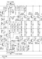
What about this output stage that I attach? It uses mosfet for the driver, connected to ouput via 22ohm resistor, and it performs darlington. What's the pro/con of using mosfet in this mosfet-bipolar darlington system compared to all bipolars triple or quadruple darlington?
Yes, you are right. Mosfet can "block" what happens with the load from entering the VAS / signal stage. Mosfets are good for classA. This time I'm making class AB where bipolars are more suitable, so I have to deal with this questionPersonally I prefer to use MOSFETs for the output stage, rendering the entire subject of triple Darlingtons moot..
Hi, Mr.Pass,
Yes, I'm making AB amp using pararel bipolar for final stageAre you running BJT's?
The rail is +/-70V, and I wanted to stable up to 2ohm. That makes about 35A max?How much current are you trying to deliver to the load?
I havent design completely, I will be using single differential. But from experimenting, If I use ordinary 3 stage power amp, it will be 2mA ccs (1mA to each leg) cause this configuration seems sound good. Haven't design the VAS yet. Will it need EF after the differential voltage drop?How much current can your front end source?
Other option is to use Folded Cascode.
At high current? The transistor is C5200+its PNP. Is this high current beta the same as the beta shown in datasheet, or we have to test it manually?How high is the beta of your output device at high current?
Since I haven't design anything yet, I dont know. The up limit is 3 stages power amp, with option of folded cascode.How sophisticated is your frequency compensation system?
What about this output stage that I attach? It uses mosfet for the driver, connected to ouput via 22ohm resistor, and it performs darlington. What's the pro/con of using mosfet in this mosfet-bipolar darlington system compared to all bipolars triple or quadruple darlington?
Attachments
sss said:i think the main problem with tripple output stage is stabilization , the gain (beta) is so high so it starts to oscilate .
its the same as making an amp with five gain stages
anyways , i think the compound config is much better then darlington.
As I used triple darlington many times, I can comment, that it's not complicated to avoid oscillation.
Just apply some base stopper resistors. I use 1-4.7ohms for the output devices (it good too if You have more output device connected parallel), 10-47ohms for the drivers, and 100-470ohms for the predrivers. I never had problem with the oscillation.
Another good thing for the triple darlington, that it provide very low output impedance without large amount of feedback. And also very easy to provide constant output impedance over the whole frequency range
sajti
Safe operating area - SOAR

You are going to need =lots= of transistors.
If the load is purely inductive (worst case, but you have to allow for these kind of things - a more reasonable real-world figure is 45 degrees) the load current will lag the voltage by 90 degrees so at the zero crossing of the output voltage at full power you will have 70/2=35 amps *and* 70 volts across the output transistors *at the same time*. 30x75=2250 watts instantaneous dissipation.lumanauw said:The rail is +/-70V, and I wanted to stable up to 2ohm. That makes about 35A max?
You are going to need =lots= of transistors.
Re: Safe operating area - SOAR
Yes. He needs at least 6pairs of MJL21193/94, or 8pairs of 2SA1943 / 2SC5200.
sajti
Circlotron said:
If the load is purely inductive (worst case, but you have to allow for these kind of things - a more reasonable real-world figure is 45 degrees) the load current will lag the voltage by 90 degrees so at the zero crossing of the output voltage at full power you will have 70/2=35 amps *and* 70 volts across the output transistors *at the same time*. 30x75=2250 watts instantaneous dissipation.
You are going to need =lots= of transistors.
Yes. He needs at least 6pairs of MJL21193/94, or 8pairs of 2SA1943 / 2SC5200.
sajti
Certainly. At 70V one of those transistors can only handle 3 amps.
http://www.onsemi.com/pub/Collateral/MJL21193-D.PDF
http://www.onsemi.com/pub/Collateral/MJL21193-D.PDF
lumanauw said:What about this output stage that I attach? It uses mosfet for the driver, connected to ouput via 22ohm resistor, and it performs darlington. What's the pro/con of using mosfet in this mosfet-bipolar darlington system compared to all bipolars triple or quadruple darlington?
What you have done is made a discrete insulated gate bipolar transistor (IGBT). They seem like a good way because you get the low gate capacitance of smaller MOSFET (providing you choose the correct device, of course) with (some of the) high transconductance and linearity of power BJT.
In my own designs with MOSFET output stages I always use a driver transistor. Many people make the mistake of thinking that a MOSFET has high input impedance so you don't need any drivers and you can parallel loads of them. The gate capacitance causes increased current demands at HF and can load up the VAS as much as a BJT in this region. This causes an increase in higher harmonics, which is really bad as there is less NFB to reduce them, and they are just plain bad anyway.
Single darlingtons are usually better in situations like the A40
You see what I mean? NP chooses to use Darlington transistor, compared to use bipolar+driver. What is wrong with using driver?
Even in threshold amps, with large Vrail, he designs with minimal driver stage.
Darlington transistor like TIP142/147 are not so rugged. Many time I found they are easily broken in several amps.
There must be something about advoiding drivers. But what is it?
Just apply some base stopper resistors.
Thanks for the tip !
the gain (beta) is so high so it starts to oscilate
If we use a transistor in a Emitor Follower mode it only magnifies current. If we use a transistor in Common Emitor mode, it magnifies both voltage and current. It makes sense that Common Emitor mode tends to oscilate with big beta. What is oscilation mechanism in EF / big beta in current magnification only?
Hi !
It's true, tripledarlington easily oscillates on capacitive loads, even
without globalfeedback. But as sajti said, simple basestoppers stop
this phenomena. My experience is that 1.2ohm at output-bjts is
already enough.
And it's a bit more tricky to get proper feedbackcompensation.
I have one mainreason to use tripledarlington, it simply enables
a lowcurrentvas, which has the advantage to enable the use of very
fast smallsignaltransistors (ft=300mhz), which also are more linear
and have higher gm than bjt's beeing able to process >10ma.
The advantage from these smallsignal-bjts is easily above the
disadvantage of the extra stage, for which i also use smallsignalbjts.
In my sims a triple-ef was always ahead, even with highcurrentvas,
except the case of r-loaded vas. (AKSA/P3A-style)
For the audible aspect, the triple-ef seems to sound more powerful,
handling reactiveloads and lowohmic effortless.
Mike
Hi, Mike,
I got 2 question
1. What do you think of Mosfet-Bipolar darlington like I attach?
2.
I got 2 question
1. What do you think of Mosfet-Bipolar darlington like I attach?
2.
What is wrong with darlington/triple darlington with R loaded VAS/bootstrapped VAS? Are they not match each other? Or you mean AKSA style is not suitable for big rating power amps?except the case of r-loaded vas. (AKSA/P3A-style)
lumanauw said:Hi, Mike,
I got 2 question
1. What do you think of Mosfet-Bipolar darlington like I attach?
2.
What is wrong with darlington/triple darlington with R loaded VAS/bootstrapped VAS? Are they not match each other? Or you mean AKSA style is not suitable for big rating power amps?
Nothing "wrong" about the R loaded VAS (bootstrapped). It simply
does not need the tripledarlington, that's all !
But i think for VERY high power the tripledarlington can be better
in this case.
I have to do some checking on the mosfet-bipolar, i have no experience
with these.
I see a problem in the big inputcapacity of mosfets, but maybe they
can even help with feedbackcompenastion ?
Mike
MikeB said:
Nothing "wrong" about the R loaded VAS (bootstrapped). It simply
does not need the tripledarlington, that's all !
But i think for VERY high power the tripledarlington can be better
in this case.
I have to do some checking on the mosfet-bipolar, i have no experience
with these.
I see a problem in the big inputcapacity of mosfets, but maybe they
can even help with feedbackcompenastion ?
Mike
I used triple darlington for bootstrapped VAS. It works good. I also used the fixed resistor at the base of the predrivers as well...
sajti
35*70? I'm sorry! my knowledge is not goodyou will have 70/2=35 amps *and* 70 volts across the output transistors *at the same time*. 30x75=2250 watts
Because loudspeakers are not purely resistive there will be either a lead (capacitive) or lag (inductive) in the current compared to the voltage.
Imagine two identical sinewaves on top of each other, one is current and the other is voltage. If one is phase shifted (lead or lag) by 90 degrees, the peak of one will coincide with the zero crossing of the other.
With a resistive load, an output transistor will be flowing max current when the output is at max voltage -- hence the voltage across the transistor is at a minimum as it's fully on. This is OK as dissipation is low (high I, but low V) and (should be) within SOA. The output transistor will have max voltage across it at the zero crossing point as it has to shield the load from the rails. Again, this is OK as dissipation is low (high V, but low I).
However, with a reactive load where current is out of phase by 90 degrees (worst case), this is bad news for an output stage as at the voltage zero crossing the current will be playing catchup with the voltage swing peak preceeding it and so be at max. So with high V and high I the dissipation is huge and the device exceeds SOA and blows.
lumanauw said:NP chooses to use Darlington transistor, compared to use bipolar+driver. What is wrong with using driver?
A darlington is simply two followers in series, and the A40
had them in a single package, as opposed to two packages,
otherwise there is not a topological difference. The advantage
of a single package is simplicity. The advantage of discrete
parts is that you can choose your parts independently, and
vary the bias of the driver as you like.
lumanauw said:The rail is +/-70V, and I wanted to stable up to 2ohm. That makes about 35A max?
If you're using BJT's, it looks like you'll want a triple. Two things
will help the stability: a good RC network to ground at the
output and use of Base resistors on the drivers, usually
something like 100 ohms on the first, maybe 10 on the second,
and maybe 1 on the outputs themselves. There's no hard and
fast rule, but this approach usually helps as an alternative to
lots of lag compensation.
- Status
- This old topic is closed. If you want to reopen this topic, contact a moderator using the "Report Post" button.
- Home
- Amplifiers
- Solid State
- Darlington and Triple darlington