Banned
Joined 2002
hello all there i have finaly taken the amp and Some what powered it up.. now here are the problems..
1st there was a flaw in anthonys schematic that he personaly sent to me he drew the 15 v zener diode in the wrong place and when i powered it up with the var-ac it blew the fuse and the diode so my dad and i looked over it and he seen that he drew it on the wrong spot. i bought myboardabout 2years ago when i got it he had drawn on the pcb overlay where the parts go..
Now i fixed that problem but there is another problem still. with or with out a input or grounded load h-f osicalations occours.. can any one please help me i am in need of help i email anthony and no responce so i am stuck..
if need the over lay let me know and ill scann it..
Please help
jleaman@citytel.net
Banned
Joined 2002
Jason,
Which zener are you referring to - is it the one that is in the shunt bias section. In any case, a scan of the component overlay and the exact part will help.
I have assembled four N-channel amplifiers, on self-designed PCBs and I have never encountered oscillation problems. Check whether the 0.33ohm resistors for the output devices are wirewound (inductive types). If so, replace them with 3x1ohm 1 watt MFR/CFR resistors. Add a Bouchoret network(Zobel) at the output consisting of 4.7ohm 5watt resistor and 33nF 400V capacitor. The network is not part of Anthony's schematic.
Waiting for your response,
Banned
Joined 2002
Banned
Joined 2002
What? No source resistors??
The last time I looked at the cct for this, each upper and lower fet had a low value resistor from it's source lead to where it is commoned with the other two. Have a look at the pic of the current pcb and see if there is a difference between it and yours.
http://www.aussieamplifiers.com/images/n-chn3.jpg
It doesn't show provision for source resistors but I seem to remember there was on the schematic...
GP.
Jason,
Ciclotron is right. On the positive side, the Drains of the output Mosfets are connected to the output via 0.33 ohm 3 watt resistors and on the negative side the Source of the ouput Mosfets are similarly connected. The temperature sensing device, which is part of the shunt bias circuit is now an IRF610 and not a BD181 as earlier. This device should be mounted in thermal contact with one of the output devices and not directly on the heatsink. Also note that three zener diodes are used in the circuit and all have been lately changed to 9.1V 1 watt from 15V.
Have you checked Anthony's site for notes on the construction of the N-channel amp?
Banned
Joined 2002
Hi Jason
You need to download the n-channel manual from my website and read it very closely. Concerning the source resistors. You need to remove the source pins from the pcb on each mosfet and insert a 0.33 Ohm 5watt resistor in each hole, with the resistor lead pointing into the air.
Then bend the the resistor lead over so you can solder the lead to the Source pin of each mosfet.
The manual says to cut tracks and connect the resistors in a different mana for the bottom side or the negative voltage side of the o/p stage. In your case I would suggest what I have told you above as it is much easier to done and it makes no difference to the performance.
Remove the 10pf cap across the 22k resistor, I think you will find that the oscillation will stop.
But do the source resistor mods before you go any further, This is a must!!
When your get to adjust the bias for the o/p stage. Measure across one of the source resistors for a measurement of 33mv, and then check the rest of them...
I Hope this helps
Regards
Anthony
Anthony,
Finding you is so very difficult, hence, while you are at it, what about the mods to increase the power of the N-channel amplifier. I am thinking of using perhaps, MPSA92/42 for the input section (lower Hfe types, I know), IRF710 for the splitter and IRFP460s (may be 6 in each bank) and raise the voltage to around 90-95volts.
Any comments? Thanks.
Jason,
Oops! I am sorry. My earlier post was made in a haste - I should have actually said that the 0.33ohm resistors are connected to the Source of the Mosfets in the positive bank and the Drains of the Mosfets in the negative bank; I said the opposite thing earlier. All the best.
I have recently built my own active subwoofer using Anthony's N-channel amplifier. I have the same problem as JasonL had a while ago with oscillation at the output. It looks like triangularwave with an amplitude of 9VRMS at 500kHz. It did instantly disappear when I put a RC-network at the output (5.6ohm in series with 220nF).
Since I know Anthony is now back I would like to ask what might cause this since he himself has had no problems with this amp.
Is it because i'm using IRFP260 as output devices (5600pF gate-cap.)?
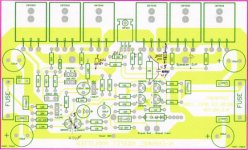
Here is some photos of the complete amp with own PCB-design:
-Pelle
Since I know Anthony is now back I would like to ask what might cause this since he himself has had no problems with this amp.
Is it because i'm using IRFP260 as output devices (5600pF gate-cap.)?
Here is some photos of the complete amp with own PCB-design:
An externally hosted image should be here but it was not working when we last tested it.
An externally hosted image should be here but it was not working when we last tested it.
-Pelle
Greetings Pelle
What a great PCB layout you have done!")
I will be changing the layout of the n-channel design to have 8 o/p devices and a zobel network using 100nf 250 volt AC mains rated MKT cap and a 5 watt 10 Ohm resistor this should fix any strange instablity problems. I think you a correct in saying that using the IRFP260 may have contributed to the instablity.
I have found that these values work very well on any power amplifier. The fact the I am using a wire wound resistor has no affect on the performance of the amplifier.
I hope this helps...
Warm regards
Anthony Holton
aholton@netspace.net.au
www.aussieamplifiers.com
What a great PCB layout you have done!
I will be changing the layout of the n-channel design to have 8 o/p devices and a zobel network using 100nf 250 volt AC mains rated MKT cap and a 5 watt 10 Ohm resistor this should fix any strange instablity problems. I think you a correct in saying that using the IRFP260 may have contributed to the instablity.
I have found that these values work very well on any power amplifier. The fact the I am using a wire wound resistor has no affect on the performance of the amplifier.
I hope this helps...
Warm regards
Anthony Holton
aholton@netspace.net.au
www.aussieamplifiers.com
I like this amp
Anthony,
I have looked at most if not all of the diy amps out there today. I don’t think that anyone can look at a circuit and instantly state how it would sound. However I do have some idea of what I am looking for. The first thing that I look for is reviews from other people who have built the amp. Whatever amp I build, I want to believe it to be the best. If heat dissipation where of no concern then I would build a pass labs AX amp, however power dissipation is of some concern to me, So I am still looking. I have also looked to see how many commercial n-channel amps there are out there, and to see what people think of them. I have found 3 the first two where bad quality amps and as a result don’t sound to be the best out there today. The last amp just came out. It is from a company called Balanced Audio Technology they are the VK-250 and VK-600. Should I post a pic ? These amps got very good reviews. More info can be found at http://www.balanced.com/ . The claim of these amps is:
Two Gain Stages,
Zero Global Feedback Design
Fully Balanced - Input to Output
Optional BAT-PAKTM with Depth Charge Oil Capacitors
All N-Channel MOSFET Circuit
Getting back to your amp Anthony, I think that it is one of the better amps out there. It got good reviews, it shows originality, and it was not designed by a newbie. I have some questions and suggestions I would like some feed back on. I don’t totally understand how the bias circuit of this amp works. The bias voltage source looks to be between the output and one side of q13. Does this mean that the bias is modulated with the signal?
It has been stated that the Highs could be improved. But no one will say what’s wrong with them. The lists of possibilities that go through my mind are, it could be rolled off, really harsh, or distorted. Could some one till me what about the highs in this amp could be improved?
May I make some suggestions for changes / improvements? I am not an EI so I hope I don’t say anything that sounds silly.
1)Make the input balanced. I think this should be an easy change to make. Even if most people don’t have balanced equipment it’s still a good idea as an upgrade path. Most amp manufactures use a small switch that grounds the (-) side of the amp when it’s hooked up to a single ended input.
2)Replace the 2SC3298 with an IRFP610. The reasoning behind this is that the 2SC3298 is getting harder to get now that it’s been discontinued. You already use the IRFP610 in the amp; this means one less transistor to track down. The cost should be about the same.
3)Balancing the circuit should also make for an improvement by lowering the noise floor and canceling distortion not common to both sides of the amp. The amp could be split at the diff pair. The other leg by q2 holds the negative signal. There would be some problems to work out; getting raid of the dc offset comes to mind right away.
i would like to build this amp too because it's quite cheap and powerfull. Can someone point me to a detailed schematic of it, because i have some problems regarding reading this schematic. And if there should be any improvements like the 9v1 zenners, i would like to know. Thank you guys!!
Attachments
palesha said:Unable to see pictures posted by Pelle in Internet explorer. What setting r required by IE6 to see them.
Palesha
Your browser has nothing to do with it, its a problem with the host where the pictures are(were) stored.
Banned
Joined 2002
I blew up my N-Channel again : O( simple mistake there was a aluminum shaving on the Heatsink under the fet pad and well dead short : O ( easy fix and also not using these thin ones any more. cant wait to fire it up.. i agree this is one of my first amps and well it still alive and good amp.. pushes some pretty impressive loads and good strong solid power.. Good job anthony..
Banned
Joined 2002
email me
jleaman at curtek . com
il send ya lots. : O ) im turning this amp into a cube mono block when all my stuff gets here for my pc setup then ill build 2 x mono block's for my home audio Or i might contact anthony see if i can buy another channel of the previouse version that i have now.. not the new one..
- Status
- This old topic is closed. If you want to reopen this topic, contact a moderator using the "Report Post" button.
- Home
- Amplifiers
- Solid State
- N-channel Problem HELPPPPPP