If I've walked into a JLH appreciation society - I apologise if my personal tastes dont fit - I just thought some alternatives exist that could be improvements
LOL
There's always a better way to improve these simple circuits.
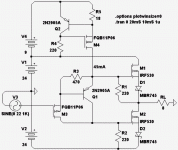
Merely replacing the bipolar output devices with MOSFETs and some
appropriate resistors from gate to source corrects a lot. Square law
vs Square law helps restore the quiescent current profile such that
the little Iq current is in the middle, and big current at the extremes.
And temperature co-efficients now bend in a much safer direction.
JLH isn't compensated or protected. Its such a poor BJT amp in
terms of bias stability that MOS-bastardrizing it actually helps.
Thats all I'm sayin. Not that you can't do far better things for
driving MOSFETs if doing so optimally was your starting intention.
"Bias servo only of use with vertical or hex", How did you come
to that astonishing conclusion? And who needs linear thermals?
We only need thermals that neither oscillate nor death spiral.
I need much more bias current for a MOSFET? OK Uh... Lets take
IRF530 for example: in PLH topology, +-24V rails, with 40mA drive
which is gonna be JLH split 20mA+20mA, amd 220ohm gate shunts.
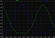
Swinging +-22V at 22KHz, I see about +-1.2mA_AC into each gate.
I'm overkilling quiescent drive current by factor of 30x above bare
minimum necessary for this mosfet. But its still less than you can
drive common bipolar output transistors.
Last edited:
"Bias servo only of use with vertical or hex", How did you come
to that astonishing conclusion? And who needs linear thermals?
We only need thermals that neither oscillate nor death spiral.
Because vertical and hex type fets experience a drop in Vgs vs Gm as they are heated, just like Vbe decreases with heat in a BJT, although not by the same means.
I need much more bias current for a MOSFET? OK Uh... Lets take
IRF530 for example: in PLH topology, +-24V rails, with 40mA drive
which is gonna be JLH split 20mA+20mA, amd 220ohm gate shunts.
Swinging +-22V at 22KHz, I see about +-1.2mA_AC into each gate.
I'm overkilling quiescent drive current by factor of 30x above bare
minimum necessary for this mosfet. But its still less than you can
drive common bipolar output transistors.
Hmm, to each his own I suppose, but for me, I don't like the extra crossover distortion presented by the sudden drop in conductance as the signal crosses the zero current point. It usually takes at least 100-200mA to significantly suppress the crossover distortion, especially with a hexfet like IRF530, or any other hexfet for that matter. Bias depends on the transconductance of the FET, but this is roughly the range for optimum bias. If the transconductance drops too far before the other device conducts, crossover distortion will appear. Any class AB bias scheme BJT or FET, is all about keeping the overall transconductance constant with current.
In my experience, much more than 300mA results in extra distortion related to the Gm doubling 'effect'.
Gate charge is dependent on frequency and change in transconductance. I like a fair bandwidth in my amps. When you measure gate current at say, 220 or 500KHz, it becomes significant. 220R gate resistor seems a bit high, but then stability related to this is highly affected by the circuit, layout and whether or not you use a gate Zobel filter. Hexfets are extremely fast compared to any BJT, thus they can become high frequency oscillators very easily. A gate Zobel gives better damping around the device and a smaller gate stopper can be used. This results in a higher effective Fc.
Just incase you were thinking I didn't do the math...
45mA, but only cause I'm abusing Schottkys to the
purpose of exaggerating up some square-lawness.
MOSFETs are square law devices, yes. But not quite
curvey enough to satisfy for this circuit today. Was
tryin to keep it Hyperbolic A, rather than let either
transistor cutoff like true AB.
45mA, but only cause I'm abusing Schottkys to the
purpose of exaggerating up some square-lawness.
MOSFETs are square law devices, yes. But not quite
curvey enough to satisfy for this circuit today. Was
tryin to keep it Hyperbolic A, rather than let either
transistor cutoff like true AB.
Attachments
I was referring to the bias current of the output FETs not the drivers. 45mA should be sufficient to provide enough charge to the gates. Also I was describing class AB as it is the most 'bastardized' design. Not having the outputs ever turn off in this way relieves a lot of issues with bias and thermal stability.
If you wish to give my designing a bashing go here http://www.diyaudio.com/forums/solid-state/160755-trying-build-omg.html
I love Dallas by the way -- spent some time at Texas Motor Speedway with Team Texas
What?! Only 12 year Scotch?

I always find when prototyping a circuit it helps to limit the supply current. It is better to see the supply voltage drop when something goes awry than to feel the burn.


You must be a much better drinker than me, I find when alcohol is involved, mistakes happen at a much higher rate.
What about at 200KHz? or 500
Sure, MOS ugly at HF... But what are we comparing it to? JLH w. BJT...
Did MOStardizing "improve" on the basic JLH? I think in this case, it did.
Yeah, I'm not surprised by the HF behavior. Mosfets need an active 'turn off' source or a lower Z drive to operate that fast. For M1, being a source follower, CISS is effectively bootstrapped so the driver may see roughly about 1/10th of the input capacitance. But M2 which is common source, needs a relatively low Z driving the gate 'turn off' action of M2, it may not turn off fast enough to prevent cross-conduction so HF is limited.
- Status
- This old topic is closed. If you want to reopen this topic, contact a moderator using the "Report Post" button.
- Home
- Amplifiers
- Solid State
- mosfet class a/ab amp

