Ok, i was browsing a classified board and found a nice Threshold s350e Amp for sale and in looking at the photo's i noticed an interesting heatsink arraingment that brought me back to my original question i posted here some time ago....
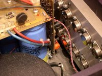
If you look at the attached photo. you will see that the TO-3 output transistors are mounted with the tops of the cans away from the outside of the heatsink on a plate of some sort that mounts to the large external heatsinks. presumably with the wiring is between this plate and the heatsinks.
Now in my previous post, i asked why i couldnt mount my transistors to a flat plate bolted between 2 large heatsinks.
So i am curious how this was done in the 350e
Mr. Pass if you have a moment...
Zero
Attachments
Mr. Zero:
I would think that as long as the trace / wire lengths were kept very short, either way would work. I only post this stab at an answer because I have been informed that Mr. Pass is very busy working on an imprtant new project and may not be available for a speedy reply to your post.
-Casey Walsh
I would think that as long as the trace / wire lengths were kept very short, either way would work. I only post this stab at an answer because I have been informed that Mr. Pass is very busy working on an imprtant new project and may not be available for a speedy reply to your post.
-Casey Walsh
Whenever you are mounting TO-3's on a big flat plate and then
attaching heat sinks to that, there are 3 ways to go that I have
commonly seen:
1) Mount the heat sinks with a gap between the heat sinks which
leaves room for the transistor can to mount from the outside of
the amp.
2) Make a set of spacer bars which create a gap between the
big flat plate and the heat sinks. This spacer must carry the
heat from the plate to the sinks.
3) Use a big extrusion which has the gap of (2) molded into it.
Threshold uses #2, and PL uses #3.
IS it possible to have too large of a heatsink for mosfets? or is it ok to go with the biggest heatsinks you can find?
I understand they need to be rated in c/w at least large enough for said design, but is there such a thing as having too big a sink?
Are there detrimental effects in doing so?
Ie: if we had a 20 watt class A amp and we mounted the the Mosfets to a piece of extrusion being 4' long 12" wide with 3" deep fins, or soemthing else thats way overkill for said design would there be detrimental effects???
Zero
Zero Cool said:IS it possible to have too large of a heatsink for mosfets?
No.
spacer plate
would it not be possible to mount the output devices straight to the spacer plate, and isolate the plate from the heatsinks ?
The thermal resistance from the Fets to the spacer would be significantly lower, the heat taken much faster to the heatsinks.
Given a large contact area of the spacer plate to the heatsinks the area of the isolation would be of the same order, creating a small thermal resistance.
Silicon sheets of ample dimensions are available.
Leaves the question of the effects of a potential on the spacer plate ?
jacco
- Status
- This old topic is closed. If you want to reopen this topic, contact a moderator using the "Report Post" button.
- Home
- Amplifiers
- Solid State
- Heatsinking ???'s Pt 2 Mr. Pass!!!