Hi all,
Some of you must remember me of one of my first threads about a year ago(http://www.diyaudio.com/forums/showthread.php?threadid=1138), it's about my first try to make an amplifier but unfornately it blew up several times, so I asked you to help me, and you did. But I stopped the project then because I was too impatient. I decided to start reading about how amplifiers work and how to design them. And I learned a lot of this site since then.
Yesterday, I took back my first (toasted) amp-pcb and I decided to redesign the schematic to delete the mistakes and to make it stable.
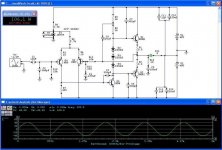
I just finished my first version, it ran smoothly in simulation, and I would like your comments on it.
NOTE:
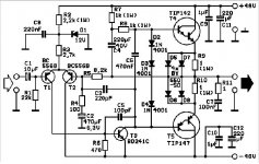
*) I'll use in the future an extra pair of transistors (MJ15003/15004) after the TIP142/147
*)the diodes must be mounted on the heatsink and not in the excisting holes in the pcb
*)the same pcb can be used
*) maybe I'll change the value of the emitter resistors to adjust the quiescent current
*)I'll recommend a small heatsink for Q5
*)I'll use a potmeter of 2.2k for R7
*)all resistors 1/4W, exceptions:
R1 & R2 => 5W
R6 & R8 => 1W
R9 => 2W
HB.
Some of you must remember me of one of my first threads about a year ago(http://www.diyaudio.com/forums/showthread.php?threadid=1138), it's about my first try to make an amplifier but unfornately it blew up several times, so I asked you to help me, and you did. But I stopped the project then because I was too impatient. I decided to start reading about how amplifiers work and how to design them. And I learned a lot of this site since then.
Yesterday, I took back my first (toasted) amp-pcb and I decided to redesign the schematic to delete the mistakes and to make it stable.
I just finished my first version, it ran smoothly in simulation, and I would like your comments on it.
NOTE:
*) I'll use in the future an extra pair of transistors (MJ15003/15004) after the TIP142/147
*)the diodes must be mounted on the heatsink and not in the excisting holes in the pcb
*)the same pcb can be used
*) maybe I'll change the value of the emitter resistors to adjust the quiescent current
*)I'll recommend a small heatsink for Q5
*)I'll use a potmeter of 2.2k for R7
*)all resistors 1/4W, exceptions:
R1 & R2 => 5W
R6 & R8 => 1W
R9 => 2W
HB.
Attachments
he, no excuse we're here to help everyoneSorry
")
I use circuitmaker, student version
you can download it freely at www.circuitmaker.com
also check this: http://www.terrypin.dial.pipex.com/ECADList.html
best regards,
HB.
I'm curious about D5-D8 in the original circuit. What are they doing? Wouldn't they cause non linearities when they start to conduct?
In the new circuit I'm wondering about C6 and C7. Are they improving anything? Also you could bypass the bias diodes with a 100 uF cap and see if that helps up the higher frequencies.
/Marcus
In the new circuit I'm wondering about C6 and C7. Are they improving anything? Also you could bypass the bias diodes with a 100 uF cap and see if that helps up the higher frequencies.
/Marcus
D5-8 is a rectifier bridge wired to bypass the 1 ohm emitter
resistors. Its purpose is to provide a low impedance path to
the load when the voltage across the 1 ohm resistor exceeds
about .6 volts. In this way, you can ballpark a bias voltage
across the resistor at less than .6 volts and not have the
bias current wander too much because 1 ohm is quite a
bit of degeneration.
Done properly, it's a viable technique, but it can be done
improperly as well.
I used it on the Threshold 800A, 400, and 4000, and later
I saw it on the "Barney Oliver Amplifier" which was an
n-house employee project at Hewlett Packard. You may
recall that Barney Oliver was a head of development at HP,
and was later deeply involved in SETI.
Yes, I was thinking about placing a cap over the bias diodes but a lot higher value than in the original circuit (470nF was too small), I think I'm going to try some different values and pick out the best.
I've made some changes to the circuit, there the original ran into oscillation of higher frequencies when no input was applied:
1) I've placed some 100nF capacitors over the transistors, and one at the input
2)I've lowered the input-impedance, and also the gain-factor by making the values of R5 and R1 equal to eachother (they must!!), and changed them to 10kohm.
3)I've placed 10 ohm resistors in the emitters of the diff.amp transistors, to handle differences of the two transistors.
4)I've changed the zobel network to the mostly used values
5)the diodes must be placed in better thermal contact with the output transistors, they are placed too far away on the PCB
6)I'm also going to use MJ15003/15004 and a bigger heatsink with a low noise fan on it.
7)I left the D5-D8 diodes away, the drills in the pcb I'll use later on to detect the voltage over the emitter resistor (for protectioncircuit, clipping-level detector, ...). I had to change the value of these resistors, and they must be 5W instead of 1W.
8)I'll use a trimpot for R6 (or R7 in the modification) there I remember there was once a DC-offset when I had changed that transistor
so what do you think about it?
HB.
In another thread (http://www.diyaudio.com/forums/showthread.php?s=&postid=40796#post40796) I recomended The Self Site (http://www.dself.demon.co.uk/index.htm). The subject of the thread is construction of a high power amp and it should be quite interesting to follow all the changes of the amp in question.
/Marcus
/Marcus
Yeah, I've just read all the 120 replies (poehh ), there are some nice ideas mentioned, I'm going to study how the inputstage with current mirror works.
back on this design:I still have the PCB and I think I will give it a first try today or tomorrow: the weather is too bad over here to go out (so time enough), I will add some flyback diodes to give extra protection.
If this works, I'll try to put a current source in the inputstage and maybe a current mirror (first have to understand that part).
see you later...
HB.
EDIT: I've changed the modification a little bit:
R3 & R4: 47 ohm
R13: 300 ohm (maybe a potmeter)
R7: potmeter adjusted at 650 ohm
input amplitude: 1,25V
please tell me if there's something wrong (could save me from the smell own blown parts )
), there are some nice ideas mentioned, I'm going to study how the inputstage with current mirror works.back on this design:I still have the PCB and I think I will give it a first try today or tomorrow: the weather is too bad over here to go out (so time enough), I will add some flyback diodes to give extra protection.
If this works, I'll try to put a current source in the inputstage and maybe a current mirror (first have to understand that part).
see you later...
HB.
EDIT: I've changed the modification a little bit:
R3 & R4: 47 ohm
R13: 300 ohm (maybe a potmeter)
R7: potmeter adjusted at 650 ohm
input amplitude: 1,25V
please tell me if there's something wrong (could save me from the smell own blown parts
)Hugo,
The current in the input differential pair is about 2.1 mA in each device, so R7 must be approx 300 Ohms in order to obtain 0.6 V to the base of the transistor...I have explained this in one another thread.
I don't understand why C6 and C7, they will cause additional phase lag, and a second pole which can easily put your amp into HF oscillation. C3 must be the unique phase lag compensation for the whole amplifier. It is possible that you have to connect a small capacitor across R12, to cause a phase avance in the feedfback, in order to obtain correct transient response with capacitive loads.
Regards, P.Lacombe
IT WORKS GREAT!!!
Yes, indeed P.Lacombe,
I did test it an hour ago, and guess.... it just worked fine.
so these are the last things I've changed before testing the amp:
I left away C6, C7, C2 (I've forgotten to place this one).
R3 and R4 are 47 ohm
R13 is 330 ohm
I've placed a 220 pF cap between the base of Q3 and the emitter of Q2 (same effect like placed over R12 ??).
I've changed the whole biasing thing into:
two diodes (2 x BYV29 - is easier to mount on heatsink) in series with a potmeter of 100 ohm, and a 470nF cap placed over these 3 components.
I've set the quiescent current to 100mA with the potmeter, checked again on DC at output (= 80mV). I connected my mixtable to the amp, and wired my speaker: worked fine at the first try. I've used too small heatsinks so I've placed two low noise fans in front of them, the temp didn't raise above 30 degrees I guess.
There is only one problem: the bass performance is excellent (I've used 2 x 37000µF) so my woofers are playing above the midrange speakers and the tweeters (I don't have this with cheap commercial amps ). When I turned of the amp the speakers kept on playing about 30 seconds (so the caps are huge enough).
Anyone idea how to reduce the bass performance, taking value of C1 between 0.1µF ====> 1µF ? I'm going to try that right now.
HB.
Yes, indeed P.Lacombe,
I did test it an hour ago, and guess.... it just worked fine
.so these are the last things I've changed before testing the amp:
I left away C6, C7, C2 (I've forgotten to place this one).
R3 and R4 are 47 ohm
R13 is 330 ohm
I've placed a 220 pF cap between the base of Q3 and the emitter of Q2 (same effect like placed over R12 ??).
I've changed the whole biasing thing into:
two diodes (2 x BYV29 - is easier to mount on heatsink) in series with a potmeter of 100 ohm, and a 470nF cap placed over these 3 components.
I've set the quiescent current to 100mA with the potmeter, checked again on DC at output (= 80mV). I connected my mixtable to the amp, and wired my speaker: worked fine at the first try. I've used too small heatsinks so I've placed two low noise fans in front of them, the temp didn't raise above 30 degrees I guess.
There is only one problem: the bass performance is excellent (I've used 2 x 37000µF) so my woofers are playing above the midrange speakers and the tweeters (I don't have this with cheap commercial amps
). When I turned of the amp the speakers kept on playing about 30 seconds (so the caps are huge enough).Anyone idea how to reduce the bass performance, taking value of C1 between 0.1µF ====> 1µF ? I'm going to try that right now.
HB.
It's probably not a good idea to reduce C1. You will raise the cut off frequency and introduce more phase shifts in the bass.
If you check the frequency response of the amp and it is flat from 20 to 20000 Hz then you know that it is the source or the speakers that introduce the extra bass. You can check the source easily with a test CD.
Try to rearrange your speakerplacement to see if you can work around the problem. Some rooms have rather high room gain.
Hope this helps.
/Marcus
Marcus,
the phase shifts aren't any problem because they're fed to the input of the amp, so there's no risk that the amp will oscillate (if you ment this). It's actually the same as an high pass filter in a mixer or whatever what application (all these filters have phase shifts).
Indeed, the problem is the speaker(s), those speakers have been build for commercial use and cannot handle the pure (unreduced) bass, actually I think that the very low frequencies (under 50Hz) are pushing the woofer too far; I've tested several speakers but always the same problem, so I'm thinking to add a kind of switch to the amp to select the input capacitor, so when using good speakers a cap of 10µF can be used (also use this if you want the pure sound), when using commercial speakers a smaller cap will be used (sound with phase shifts in reduced bass).
room-acoustic:
Indeed, I tried this before when the speakers are placed on the floor in a corner there is an amazing bass performance). But the problem is not that the speaker plays too loud but is driven too far (with not that much sound) in comparison with the two other speakers, so again I guess, that the VLF (very low freq) are the major problem. The problem doesn't excist when an amp with a supply with small caps is used.
HB.
I didn't mean oscillations of the amp, sorry for being unclear.
I meant that if the high pass filter is set to have its cut off at 20 Hz, then the phase is 45 degrees off at that frequency. It doesn't reach 0 degrees untill the frequency is approx. 200 Hz.
I'm not so sure that one can hear the difference between 20 Hz cut off and 5 Hz cut off, though. Just thought I should mension it.
/Marcus
yep, I thought so
but what about a cutoff at higher frequencies? So the 45° phase shift at higher frequency? OK, the output of the amp will not be 100% the same as the source output, but I think this will do the job (with this kind of speakers of course).
I just give it a try, a cap is quickly changed...
HB
but what about a cutoff at higher frequencies? So the 45° phase shift at higher frequency? OK, the output of the amp will not be 100% the same as the source output, but I think this will do the job (with this kind of speakers of course).
I just give it a try, a cap is quickly changed...
HB
- Status
- This old topic is closed. If you want to reopen this topic, contact a moderator using the "Report Post" button.
- Home
- Amplifiers
- Solid State
- FINALLY I modified it