Hi All,
This is my first post, so I hope it works ok!
While reading this thread:
much less crazy idea
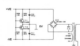
I noticed the talk of generating floating grounds with big resistors, which reminded of the scheme that Quad used for their 306 amplifer (amongst others, I'm sure). By putting 2 smoothing caps in series, the voltage at their midpoint is roughly equal to half the total supply voltage. To ensure that it remains close to this point, two transistors are used to steer the point to the required voltage. This then forms the signal ground for the whole amplifier.
This arrangement offers DC protection for the loudspeaker - if one of the output devices saturates. the midpoint will be allowed to rise to the appropriate tail, thus avoiding damage to the speaker. The only drawback of this is both capacitors must be rated to the total supply voltage (unlike a conventional split supply, of course)
Hopefully, this might be useful if you happen to have a large mains transformer with a single winding...? Apologies if everyone already knows this!
BTW, click here for the
complete Quad 306 schematic")
This is my first post, so I hope it works ok!
While reading this thread:
much less crazy idea
I noticed the talk of generating floating grounds with big resistors, which reminded of the scheme that Quad used for their 306 amplifer (amongst others, I'm sure). By putting 2 smoothing caps in series, the voltage at their midpoint is roughly equal to half the total supply voltage. To ensure that it remains close to this point, two transistors are used to steer the point to the required voltage. This then forms the signal ground for the whole amplifier.
This arrangement offers DC protection for the loudspeaker - if one of the output devices saturates. the midpoint will be allowed to rise to the appropriate tail, thus avoiding damage to the speaker. The only drawback of this is both capacitors must be rated to the total supply voltage (unlike a conventional split supply, of course)
Hopefully, this might be useful if you happen to have a large mains transformer with a single winding...? Apologies if everyone already knows this!
BTW, click here for the
complete Quad 306 schematic
Attachments
The problem is that this is the same as a capacitor coupled speaker, only the capacitors are placed differently. All the speaker current still have to go through the capacitors and they need to be highly ripple tolerant.
But it is an interesting schematic.
I didn't get the quad link to work, though.
/Marcus
But it is an interesting schematic.
I didn't get the quad link to work, though.
/Marcus
Sorry about that!
Try this instead
The Quad306 link is towards the end of the list...
I wondered about the sonics, as it does appear to be equivelent to a simple series capacitor at a first glance. But, as the signal is referenced to this floating ground, I guess that feedback should help...
Try this instead
The Quad306 link is towards the end of the list...
I wondered about the sonics, as it does appear to be equivelent to a simple series capacitor at a first glance. But, as the signal is referenced to this floating ground, I guess that feedback should help...
Digging up this rather old thread!
I want to use this schematic to run a chip amp that needs a dual-rail supply from a single-rail laptop type SMPS.
1) Will it likely be okay hanging off the end of an AMPS, or does this only work with a standard linear PSU?
2) Those transistors are not around these days, what would be a good (affordable) alternative? My amp is only 25watts so maybe less power capable transistors could be used than in the Quad. I thought maybe NXP BCP53-10 to replace ZTX750. BCP56-10 to replace ZTX650? I don't know much about choosing transistors but they have similar voltage rating and HFE and 1A compared with the ZTX 2A current handling.
Thanks!
My 306 amp is fitted with ZTX653/753 and these can replace any in the ZTX65X/ZTX75X range of parts which only vary by Vceo/Vcbo. Note other models in the 306,606,707,909 series use such other parts too. e.g: Quad 909 Manual - Stereo Power Amplifier - HiFi Engine......2) Those transistors are not around these days, what would be a good (affordable) alternative? My amp is only 25watts so maybe less power capable transistors could be used than in the Quad. I thought maybe NXP BCP53-10 to replace ZTX750. BCP56-10 to replace ZTX650? I don't know much about choosing transistors but they have similar voltage rating and HFE and 1A compared with the ZTX 2A current handling.
Thanks!
You do know that this is likely to result in rather considerable capacitive coupling to mains, inviting ground loop issues?Digging up this rather old thread!
I want to use this schematic to run a chip amp that needs a dual-rail supply from a single-rail laptop type SMPS.
I would expect a SMPS to be somewhat unhappy with capacitor values as shown. The circuit also implicitly assumes non-zero output impedance.1) Will it likely be okay hanging off the end of an AMPS, or does this only work with a standard linear PSU?
A splitter like that with two capacitors of value C is about equivalent to having output coupling capacitors of somewhat less than 1/4 C in a stereo amp. I.e. here you'd have the effective equivalent of about 1000 µF output coupling caps.
It's generally a better idea to properly convert the circuit to singly-supply operation. If you already have a PCB intended for split supply operation, tough luck. Either get another for singly supply or obtain a proper split secondary transformer. Stacking two switching supplies may be an option, but it would depend on the specifics of the supplies used, and I am not sure whether it's a good idea.
You do know that this is likely to result in rather considerable capacitive coupling to mains, inviting ground loop issues?
I would expect a SMPS to be somewhat unhappy with capacitor values as shown. The circuit also implicitly assumes non-zero output impedance.
A splitter like that with two capacitors of value C is about equivalent to having output coupling capacitors of somewhat less than 1/4 C in a stereo amp. I.e. here you'd have the effective equivalent of about 1000 µF output coupling caps.
It's generally a better idea to properly convert the circuit to singly-supply operation. If you already have a PCB intended for split supply operation, tough luck. Either get another for singly supply or obtain a proper split secondary transformer. Stacking two switching supplies may be an option, but it would depend on the specifics of the supplies used, and I am not sure whether it's a good idea.
Hi,
Can you explain more about the capacitive coupling to mains, please? I thought the SMPS is totally isolated from the mains side by the switching TX.
I can design a single rail circuit, however it would IMO be easier to split the supply to dual-rail because I have other line level bits to run as well as the amp. If I converted the amp to a single rail design it would need output AC coupling caps anyway, so whether they are on the output or in the PSU doesn't matter a lot to me.
I'd like to try it and see how it does. If it doesn't test well I'll change my tune.
My 306 amp is fitted with ZTX653/753 and these can replace any in the ZTX65X/ZTX75X range of parts which only vary by Vceo/Vcbo. Note other models in the 306,606,707,909 series use such other parts too. e.g: Quad 909 Manual - Stereo Power Amplifier - HiFi Engine
Thank you!
You could build a 'full bridge' amplifier, that is, an amplifier with balanced output. Think of it as two bridged mono amplifiers at 180 degrees output, or better yet, a balanced amplifier circuit. Then there would be no need for an output coupling cap. You could use DC servos for each phase input set at 1/2Vcc, so as the speaker sees 0VDC between the two output nodes. Could easily make a DC detector between the outputs to trigger protection logic. Perhaps a tiny bit more complex , but the concept is sound.
(pun intended)
You could use DC servos for each phase input set at 1/2Vcc, so as the speaker sees 0VDC between the two output nodes. Could easily make a DC detector between the outputs to trigger protection logic. Perhaps a tiny bit more complex, but the concept is sound.(pun intended
)For EMI reasons, SMPS' without a protective earth connection (e.g. figure-8 connector) usually implement a Y-rated capacitor in the order of 1 nF between secondary-side ground and mains return, or two of them to mains phase and return. Otherwise common-mode radiation would be an even bigger problem, I guess.Hi,
Can you explain more about the capacitive coupling to mains, please? I thought the SMPS is totally isolated from the mains side by the switching TX.
Supplies that do come with a protective earth connection (which would allow draining mains filter currents primary-side) may connect secondary-side ground to PE, or may opt to use a resistor of about a 1kOhm, presumably in parallel with some capacitance (found for some Thinkpad PSU, IIRC).
Those are the dirty little secrets of SMPS' in audio. If you want minimal capacitive coupling to mains, an old-fashioned xmfr with a shield winding still is the way to go.
As for the above suggestion, actually a lot of single-supply amplifier designs are BTL (loads of Class Ds and AB car amplifiers). The only drawback is that each amplifier has to drive half the load impedance, and as gain effectively increases by 6 dB, so does noise.
Last edited:
Thanks for the detailed explanation.
Forgive me if I've misunderstood but you are saying the capacitive coupling to mains is simply part of the SMPS design, not caused by hanging my rail splitter circuit on the end of it? If I were running single rail it would still couple my amp supply to mains by a capacitor right?
Forgive me if I've misunderstood but you are saying the capacitive coupling to mains is simply part of the SMPS design, not caused by hanging my rail splitter circuit on the end of it? If I were running single rail it would still couple my amp supply to mains by a capacitor right?
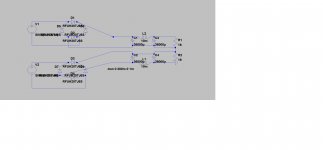
This is actually not the same as the OP's problem. Your SINE sources are independent transformer secondaries, right? This is a split power supply with a different ground reference node, so it should basically be working fine and give the same performance under the same loading. However, unless you're voltage-limited, you may find that complexity can be reduced substantially by just stacking the secondaries on top of each other, leaving you with only one rectifier bridge and one set of filters.Just to make sure we are on the same page,you are saying this diagram is a no no.
Reviving this old thread again
I have a pair of single secondary toroid's from scrapped bench supplies that I would like to re-use for a dual mono amp, and thought about doing something similar to the Quad solution in the first post. However my intention was to make it 'sturdier' like a EF output pair with low value emitter resistors, but had not made any sims.
Then I found this thread, and it got me thinking about it. It might make more sense to have a 'weak' midpoint 'DC control' like the Quad, no DC protection on the output, so the current to the speaker would be limited in case of an amp failure with DC on the output?
Caps will handle the AC impedance of the supply (4x22mF/channel), and DC impedance can be higher, but still striving to keep the center tap centered with limited current capability.
Suggestions or variations on the theme are welcome, just to give me some ideas!
How does it protect from DC?DC protection
If an output device went short-circuit, would not the entire energy of one capacitor still go through the speaker?
- or is that 'better than continuous' so a type of protection?
Yes, it would, and with large caps like this it could still smoke the voice coil depending on what speaker is connected.
Continuous DC is worse than momentary and current limited continuous is better than unlimited
Amps with output caps rarely need/have DC protection for the same reason.
Continuous DC is worse than momentary and current limited continuous is better than unlimited
Amps with output caps rarely need/have DC protection for the same reason.
- Home
- Amplifiers
- Solid State
- Artificial floating ground