pejinm said:Chao davorinjo,
No, the signal ground and supply ground are not on the same potencial. They are separeted by 10ohm resistor on the board. You can find GND socket on board layout behind relay and use this ground to connect transformer.
Pozdrav...
Pozdrav!
Is this ground socket used also for "speaker ground", or do I connect the speaker on "input ground".
tnx
Hi,
create a floating audio ground.
connect all of the following to the audio ground.
signal ground from PCB,
possibly input RCA ground,
power ground from PCB,
speaker return,
Zobel/Thiel return,
smoothing cap 0volt (common),
transformer centre tap (single wire)
disconnecting network from the safety earth/chassis.
The audio ground and the input RCAs and the speaker return should all be isolated from the chassis.
Right now I am measuring 22.6 V DC on output with no signal applied and no load, with 22ohm 5w resistors in place of the fuses.
Supply rails are 2 x 37v DC for now (using 25-0-25 trafo for testing)
It doesn't look right -> dc on output, right?
btw. I bypassed dc protection
Davor
Supply rails are 2 x 37v DC for now (using 25-0-25 trafo for testing)
It doesn't look right -> dc on output, right?
btw. I bypassed dc protection
Davor
Could somebody tell me why am I registering -34V between Speaker and GND (gnd on higher potential).
I checked for bad soldering - nothing came up.
Would this happen if T10 was fried, am I on the right track? Which component should I check first?
I am pretty green at debuging. Tnx for any help
I checked for bad soldering - nothing came up.
Would this happen if T10 was fried, am I on the right track? Which component should I check first?
I am pretty green at debuging. Tnx for any help
Hi Davorinjo,
Are you sure C13 survived? I would change it anyway.
Looks like your amp is faulty so you need to fault find it in a systematic way.
Without power or speaker connected; go over the board carefully in case there are any errors. If you used different transistors in the first stage check the pin-outs.
Then make sure that all the FETs are insulated from the heatsink by measuring from drain to the heatsink.
Then measure drain to source on each FET bank to make sure they're normal.
Also check that all the driver transistors are insulated from their heatsink.
If this checks out ok measure some voltages around the board using the schematic I posted with the current flows.
http://www.diyaudio.com/forums/attachment.php?s=&postid=818662&stamp=1137491636
Using ohms law you should be able to figure out what most of the voltages should be.
If you like post some details of what you find here and also post details of your build, I.e. transistors used, voltage rails, maybe a photo etc,
Good Luck & Cheers
Q
Quasi,
I built a 3 pair FET version of your amp using IRFP450s and used my own PCB layout. The power supply is + - 63VDC with a capacitance of 37,500uF per rail. I will soon post some pictures.
I have one question. There is audible high frequency distortion, almost like hard clipping, when played at even low volume levels into speakers systems with dome tweeters, but performs well when played into piezo tweeters.
All component values are as per published schematic except that for the zobel I have used 100nF at output and 10E 5W to ground.
In addition, I have also inserted in series a diode IN4007 and 100E 2W resistor, in both supply lines breaking the input stage and driver/output stage. The drop in voltage for the input stages is a little over 2 volts. This line is decoupled with 100uF and 0.1uF caps.
Any idea what could be causing this clipping/overload like characteristics?
Thanks,
Hi Quasi,
I'm glad you interested.
I'm very satisfied with the amp it runs very stable without any distortion. I'm planing to add more caps to the supply (have only 4x4700/100V). Also I added clipping indicator that work very nice, and saves speakers too") .
.
I have an idea to build a 10 fet version and integrate it to 15" DIY subwoofer that I planing to build too.
Having trouble to figure it out the cooling system, maybe basreflex air turbulence?
Ofcourse you will all know about when I start building
Cheers to you too dear Quasi!!!
I'm glad you interested.
I'm very satisfied with the amp it runs very stable without any distortion. I'm planing to add more caps to the supply (have only 4x4700/100V). Also I added clipping indicator that work very nice, and saves speakers too
.I have an idea to build a 10 fet version and integrate it to 15" DIY subwoofer that I planing to build too.
Having trouble to figure it out the cooling system, maybe basreflex air turbulence?
Ofcourse you will all know about when I start building
Cheers to you too dear Quasi!!!
Samuel Jayaraj said:Quasi,
I built a 3 pair FET version of your amp using IRFP450s and used my own PCB layout. The power supply is + - 63VDC with a capacitance of 37,500uF per rail. I will soon post some pictures.
I have one question. There is audible high frequency distortion, almost like hard clipping, when played at even low volume levels into speakers systems with dome tweeters, but performs well when played into piezo tweeters.
All component values are as per published schematic except that for the zobel I have used 100nF at output and 10E 5W to ground.
In addition, I have also inserted in series a diode IN4007 and 100E 2W resistor, in both supply lines breaking the input stage and driver/output stage. The drop in voltage for the input stages is a little over 2 volts. This line is decoupled with 100uF and 0.1uF caps.
Any idea what could be causing this clipping/overload like characteristics?
Thanks,
You should not be getting any distortion at high frequency. Can you please show me on the schematic exactly where you have placed the diode and 100R resistor.
Cheers
Q
My Attempt at Adding Balanced Inputs
Ok,
Lets make it clear to start I have not tested the Balanced Input addition I made to the quasi "official" current schematic (nchan mos schematic only 06-05-06.pdf).
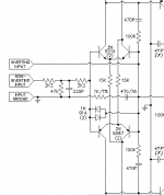
I have attached my attempt to add Balanced Inputs to the current quasi schematic using my still rooky knowledge and lots of emulating of a very well known designer's implementation for Balanced and Unbalanced inputs. My assumpution, which could be completely wrong, was I could use the LTP even though the designs I have looked at so far do not have the current mirror pair the quasi design has.
Please note that part of implementing this design attempt by me was I flipped the NFB R (R18) and C (C7) leg to ground. For clarity I added a "+" mark to C7 for those that choose to use an electrolytic or cannot find a Bi-Polar or non-polar capacator for C7.
Understand I have no design knowledge with respect to balanced lines at all, and very limited design knowledge. I have not tested this implementation of the Balanced Input. That said comments, refinements, design enlightenment and any willing soles that can test this if this first crack looks reasonable are welcome.
A side question results form the NFB RC leg to ground. I have noticed some designs over the months for the NFB RC to ground leg will order like quasi has done, R-C-Gnd, while other designs order it C-R-Gnd. Is there a reason why one order is chosen over other? As I can deduced at moment the R-C-Gnd order may allow the C when electrolytic to see a reduced DC offset voltage that it has to cope with, whereas with a BiPolar or non-Polar capacitor the design decision may be more related to using a smaller voltage C. Are any of my deductions valid?
Regards,
John L. Males
Willowdale, Ontario
Canada
15 December 2006 17:22
15 December 2006 17:27 Typo Corrections
Ok,
Lets make it clear to start I have not tested the Balanced Input addition I made to the quasi "official" current schematic (nchan mos schematic only 06-05-06.pdf).
I have attached my attempt to add Balanced Inputs to the current quasi schematic using my still rooky knowledge and lots of emulating of a very well known designer's implementation for Balanced and Unbalanced inputs. My assumpution, which could be completely wrong, was I could use the LTP even though the designs I have looked at so far do not have the current mirror pair the quasi design has.
Please note that part of implementing this design attempt by me was I flipped the NFB R (R18) and C (C7) leg to ground. For clarity I added a "+" mark to C7 for those that choose to use an electrolytic or cannot find a Bi-Polar or non-polar capacator for C7.
Understand I have no design knowledge with respect to balanced lines at all, and very limited design knowledge. I have not tested this implementation of the Balanced Input. That said comments, refinements, design enlightenment and any willing soles that can test this if this first crack looks reasonable are welcome.
A side question results form the NFB RC leg to ground. I have noticed some designs over the months for the NFB RC to ground leg will order like quasi has done, R-C-Gnd, while other designs order it C-R-Gnd. Is there a reason why one order is chosen over other? As I can deduced at moment the R-C-Gnd order may allow the C when electrolytic to see a reduced DC offset voltage that it has to cope with, whereas with a BiPolar or non-Polar capacitor the design decision may be more related to using a smaller voltage C. Are any of my deductions valid?
Regards,
John L. Males
Willowdale, Ontario
Canada
15 December 2006 17:22
15 December 2006 17:27 Typo Corrections
Attachments
AndrewT said:Hi K,
sorry, that ain't right.
Go have a look at Borbely or Pass to see how to implement the balancing of an LTP input stage.
Hi Andrew,
Before I posted the quasi amp schematic with my attempted Balanced Input addition I had been searching high and low for examples and any other information to enable me to add a balanced input. There are lots of stand alone circuits, many for microphones as that is a common venue. This meant less pickings for line level examples and information. I was trying to avoid adding a additional standalone circuit which enough examples and and proven designs existed. There was only one example I found that was part of the input stage which the schematic I posted in Post # 1235:
http://www.diyaudio.com/forums/showthread.php?postid=1082862#post1082862
was a result of.
With the hints you provided I searched yet again high and low (no balanced pun intended) and still came up with nothing despite my many efforts and kills at searching and digging. I could not even find any design information from either. Do you have any links, hints, or seach criteria that could help be find what you are referring to? It would be most appreciated as I have been doing research on this for well over a year.
I decided to be very creative in my searching and I found a very different topology design I have not even seen in standalone drivers. I have attached the implemented topology design so you can advise me if this is the topology design you had in mind?
Frankly speaking I think the initial one I added to the quasi schematic is more appealing. Is your objection to the one I made an attempt to implement unaceptable because the balanced side input has no HP/LP filter and DC blocking on its hot input?
Regards,
John L. Males
Willowdale, Ontario
Canada
16 December 2006 16:48
16 December 2006 16:55 Typo Correction
Attachments
- Home
- Amplifiers
- Solid State
- Power amp under development