For Upupa Epops;
Hey Upupa Epops;
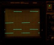
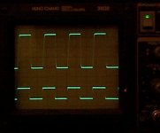
Piccy of square wave response at 1khz into 8 ohm resistive load taken at near rail to rail swing.
Cheers
Upupa Epops said:Have you any detailed pic of square wave ( 10 kHz ) into eight Ohm ? Or eight Ohm with parallel 100 n cap ? 3 dB bellow clipping ?
Hey Upupa Epops;
Piccy of square wave response at 1khz into 8 ohm resistive load taken at near rail to rail swing.
Cheers
Attachments
Hey Upupa Epops;
No I didn't. I just connected the output of my signal generator to the power amp input so the signal is just terminated by the input impedance of around 33kohms.
Is there a better way?
Cheers
Upupa Epops said:To quasi : Have you connected amp with generator by line with correct characteristic impedance ? I see on input small overshoots.
No I didn't. I just connected the output of my signal generator to the power amp input so the signal is just terminated by the input impedance of around 33kohms.
Is there a better way?
Cheers
Hey keypunch / John;
1. Yes you can use 1 or 2 pairs of FETS in this design. Without doing any calculations I would say you could use 6 or more pairs.
2. You can use almost any power FET. As a guide FETS with a lower gate capacitance will provide better performance. No schematic changes would be required unless you changed the rail voltages significantly. If the rail voltages were increased then attention may need to be paid to the voltage rating and power dissipation of the input and driver transistors
3. The values of the Zobel network (correct name) are not that critical. The network is intended to prevent RF from entering the amp from the speaker leads. It also provides loading to the output stage for high frequency helping to dampen any potential for oscillation. Many purists don’t like this network, personally I always use it.
4. No coil is needed when driving a subwoofer if you are using a low pass filter before the power amp. Some people also use a coil in conjunction with a resistor and capacitor across the woofer to modify its impedance and response. Whether a crossover (properly designed) is used with a multi-driver speaker or whether a full range is used without a crossover is entirely up to you.
5. I use this symbol (empty triangle) to indicate the “quiet” ground for the signal path from the “noisy” or power supply ground.
6. Yes pretty much. The power delivered is based on the capability of the power supply and the safe operating area of the FETS. The circuit as it stands should deliver near 400 watts into 4 ohms with the right power supply. For driving into 2 ohms I would add 2 more pairs of FETS.
7. Each amp module draws about 20 watts at idle. Other control circuitry that will be added (DC detect protection and soft turn on) will use about 2 watts per channel. Add about 10 watts for the transformer idling and you have about 50 – 60 watts of idle power ( 200mA – 250mA @ 240 volts).
8. Expected amplifier power output from a perfect amp and a perfect power supply is calculated by;
(DC rail voltage * 0.707)² / speaker impedance
E.g. (60 volt rails * 0.707) ² / 8 ohms = 225 watts RMS
The amp cct described in this thread could indeed be used for a multi-channel system and can be used with differing supply rails. You could use lower rails and less output devices for the mid and treble and a higher rails with more output devices for the bass. How much power you allocate to each amp will depend mainly on your crossover frequencies and will be an estimate in the end because it will depend on the signal content you listen to. I would personally run 100 watts per channel for the mid and treble combined and about 300 watts per channel for the bass.
I use DOS (yes DOS) based PCB and schematic design software and there is no easy way of posting these designs. I currently print them then scan them. This is why they look bad. Oh well ……
I hope I have provided some meaningful information. Contact me any which way if I have missed anything.
Cheers
Re[03]: Some Questions and Offer to Help Improve Schematic Image Files
Quasi,
Thanks for your excellent answers to my questions. I have couple follow-up questions of your answers I need clarification on:
2) With respect to "As a guide FETS with a lower gate capacitance will provide better performance." from the mosfet specs is one of Ciss, Coss, Crss the gate capacitance? If not what is the usual designation in the spec for gate capacitance? I have looked high and low now and in past to find out what in spec states or provides the information from which gate capacitance can be calculated.
6) Would it be fair to say with the current 3 pair of output drivers and ideal power supply that 200W in 8 ohms is possible? If so then basically are we talking 65W into 8 ohms per device (ignoring what is possible with one device at 4 or 2 ohms)? If I get to point of making my system active I likely use one or two output devices, and likely I would use an IFR240N or IRF250N. One device for the mid or tweeter, and likley have midrange no more than 60W in 8 ohms, but for reserve and flux of speaker impedance like to have reserve of 120W in 4 ohms. If I am forced to use a 4 ohm driver I want 240W reserve to 2 ohm for variences in driver impedance. If I could not have the 240W reserve then I will in all likelyhood not use a 4 ohm mid driver. Tweeter would not likely have more than 25W 8 Ohms (50W reserve fo r4 ohms) output acheived via a reduced power supply and exact same drivers. Later if I felt a better choice of output driver suited the tweeter amp I likelyhave many more choices at that power level.
7) Excellent for idle. Any idea how scales up once amps start to actually do something?
It is ok, I still know what DOS is. I date back much farther than PC DOS Does your DOS based software allow you to print to a Postscript printer? My memory is rusty, but I seem to recall CAD based software might also be able to print to HPGL or Laserjet PCL files. I know you likely do nto have a Postscript printer, that is quite ok, all that is important is if the CAD program can print to Postscript, not if you have a Postscript printer. Same holds true for HPGL or LaserJet PCL, no need to have, just if program is able to print to one if had one. If the DOS program can print to a postscript printer, then there are many ways to likely obtain a higher image quality in the .PNG, .GIF or .PDF than you have generated to date from the DOS based CAD program. If cannot print to Postscrip be can to HPGL or Laserjet PCL good possible solutions exist.
Do you scan with DOS or Windows? Do you run the CAD program in a Windows DOS window? If yes to the last, and program can print to Postscript then this will make things much easier than running DOS only PC, though not that much more.
Regards,
John L. Males
Willowdale, Ontario
Canada
12 December 2004 13:49
Quasi,
Thanks for your excellent answers to my questions. I have couple follow-up questions of your answers I need clarification on:
2) With respect to "As a guide FETS with a lower gate capacitance will provide better performance." from the mosfet specs is one of Ciss, Coss, Crss the gate capacitance? If not what is the usual designation in the spec for gate capacitance? I have looked high and low now and in past to find out what in spec states or provides the information from which gate capacitance can be calculated.
6) Would it be fair to say with the current 3 pair of output drivers and ideal power supply that 200W in 8 ohms is possible? If so then basically are we talking 65W into 8 ohms per device (ignoring what is possible with one device at 4 or 2 ohms)? If I get to point of making my system active I likely use one or two output devices, and likely I would use an IFR240N or IRF250N. One device for the mid or tweeter, and likley have midrange no more than 60W in 8 ohms, but for reserve and flux of speaker impedance like to have reserve of 120W in 4 ohms. If I am forced to use a 4 ohm driver I want 240W reserve to 2 ohm for variences in driver impedance. If I could not have the 240W reserve then I will in all likelyhood not use a 4 ohm mid driver. Tweeter would not likely have more than 25W 8 Ohms (50W reserve fo r4 ohms) output acheived via a reduced power supply and exact same drivers. Later if I felt a better choice of output driver suited the tweeter amp I likelyhave many more choices at that power level.
7) Excellent for idle. Any idea how scales up once amps start to actually do something?
It is ok, I still know what DOS is. I date back much farther than PC DOS
Does your DOS based software allow you to print to a Postscript printer? My memory is rusty, but I seem to recall CAD based software might also be able to print to HPGL or Laserjet PCL files. I know you likely do nto have a Postscript printer, that is quite ok, all that is important is if the CAD program can print to Postscript, not if you have a Postscript printer. Same holds true for HPGL or LaserJet PCL, no need to have, just if program is able to print to one if had one. If the DOS program can print to a postscript printer, then there are many ways to likely obtain a higher image quality in the .PNG, .GIF or .PDF than you have generated to date from the DOS based CAD program. If cannot print to Postscrip be can to HPGL or Laserjet PCL good possible solutions exist.Do you scan with DOS or Windows? Do you run the CAD program in a Windows DOS window? If yes to the last, and program can print to Postscript then this will make things much easier than running DOS only PC, though not that much more.
Regards,
John L. Males
Willowdale, Ontario
Canada
12 December 2004 13:49
Hello JWB:
In reply to: post #57
http://www.diyaudio.com/forums/showthread.php?postid=505269#post505269
can you post a schematic of the protection part which is on the pcb in this post?
Thank You in advance.
Nexus
In reply to: post #57
http://www.diyaudio.com/forums/showthread.php?postid=505269#post505269
can you post a schematic of the protection part which is on the pcb in this post?
Thank You in advance.
Nexus
Unhappy Quasi
Quasi is unhappy;
Well I have spent (wasted?) a lot of time trying to get this amp to clip symmetrically by using split & higher rails to the driver stages.
The problem I had (maybe common to all quasi-comp MOSFET amps) is that the positive signal swing clipped around 4 to 5 volts before the negative swing.
Well I succeeded in fixing it. I thought by using a higher rail for the driver stages (particularly the positive rail) I now have the negative rail clipping some 10 volts before the positive swing. and the clipping isn't as clean.
What gives??
The amp runs best with common rails all tied together (even with the positive signal swing clipping first).
Do any of you learned gentlemen and ladies have any thoughts?
One thought that had was shifting Q8's collector from the output rail to positive rail.....but this will double the voltage across it.
Hmm....please help......please?
This is the latest cct.
Quasi is unhappy;
Well I have spent (wasted?) a lot of time trying to get this amp to clip symmetrically by using split & higher rails to the driver stages.
The problem I had (maybe common to all quasi-comp MOSFET amps) is that the positive signal swing clipped around 4 to 5 volts before the negative swing.
Well I succeeded in fixing it. I thought by using a higher rail for the driver stages (particularly the positive rail) I now have the negative rail clipping some 10 volts before the positive swing.
and the clipping isn't as clean.What gives??
The amp runs best with common rails all tied together (even with the positive signal swing clipping first).
Do any of you learned gentlemen and ladies have any thoughts?
One thought that had was shifting Q8's collector from the output rail to positive rail.....but this will double the voltage across it.
Hmm....please help......please?
This is the latest cct.
Attachments
keypunch,
IRFP250N has about the same SOA as the older IRFP240. A single pair of these will give you 120 watts into 8 ohms. If you can get IRFP250 (not N version) that will give you even more. I'm talking genuine IR parts only.
Ciss is the capacitance figure you should be concerned about. Also check Qg which is gate charge. You want this to be as low as possible and it's a better thing to use than input capacitance, which is quite non-linear.
quasi,
Your amp is having problems when you use higher driver section rails because the lower half of the output stage has a little gain (yes, I know the feedback results in overall unity gain) thus can swing almost to the rail. So if you move the operating point for the driver of the lower rail to a higher voltage it begins to saturate the MOSFET much earlier as it's referenced to a higher point, as you have found. The only solution with this output topology is to use a higher positive rail only.
If you move the collector of Q8 to the positive rail you ruin the whole feedback around the driver/op and end up with an unstable (both thermally and electrically) amp.
Hey keypunch;
I'm glad my earlier response was useful. My thoughts on your follow up post are as follows and are based on a class AB amplifier.
2) I regard the input capacitance Ciss as the most important. This is what the driver stage has to charge and discharge. The other thing about this specification is that manufacturers generally specify it's lowest value. I.e. for an IRFP450 Ciss is 2700pf when there is 50 volts across drain to source, but it rises to 5300pf or more when the FET is fully on. Logically the lower the input capacitance the easier it is to drive with linearity.
6) I would bank on 100 watts per pair of devices into 8 0hms and in my design I could have got away with probably 2 pairs. I added the 3rd pair in order to take a prolonged sine wave test into 4 ohms. This type of signal is way harder on an output stage than any type of music and after a few minutes creates hot heatsinks. In terms of average power, even really demanding music probably only stretches an amp to 30% of it's rated capacity. For music sources I would be quite comfortable with 2 pairs of IRFP450's running 40 volt rails into 2 ohms. Any sine wave testing with this setup though should be restricted to a few seconds at a time. For your Mids and Tweeters one device would be heaps, you could even use a smaller FET here with lower Ciss.
7) Rough rule of thumb (very rough because it depends a lot on circuitry) when the amp is flat out would be 70% of the total power consumed is delivered to your speakers. I.e. a 200 watt amp would be consuming about 290 watts. This extra 90 watts is dissipated as heat into the heatsinks. The amp is even less efficient at half power with closer to 60% of the consumed power delivered to the speakers. There are other losses in the power supply and I allow up to 15% depending on the transformers regulation and other losses. A 200 watt per channel class AB amp would consume about 650 watts (570 watts by the amp modules and 15% more in the power supply).
My DOS software does not create postscript files. I dunno maybe I should invest in some new software, but who's got time to learn new software ? .....maybe I should ...
Hey richie00boy;
Do you mean just the rail feeding the driver stages or one rail including the outputs.
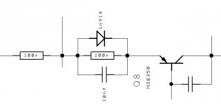
The other thought I had was this network on Q8's collector. I have just tried it and it seems to make the clipping more symmetrical within a volt or so. My theory was to add 4 volts between Q8 and the output.
Hmm....I don't like it though.
The only solution with this output topology is to use a higher positive rail only.
Do you mean just the rail feeding the driver stages or one rail including the outputs.
The other thought I had was this network on Q8's collector. I have just tried it and it seems to make the clipping more symmetrical within a volt or so. My theory was to add 4 volts between Q8 and the output.
Hmm....I don't like it though.
Attachments
There wouldn't be any point making the output device run off a higher rail. The problem arises because you can't even get near to saturation with the upper rail, but you can pretty much fully saturate the lower rail.
Your additional circuit aids linearity, it's a good addition. Get rid of the diode and you will probably see an improvement. The capacitor used should attempt to mirror the upper output device Ciss. The diode is only any real use when using BJTs.
I don't understand your comment about adding voltage between Q8 and output. However, hopefully now you understand that the problem lies in the upper rail and that preventing the lower rail from saturating is a bad way to go.
Re: Hey keypunch;
richie00boy and quasi,
Thanks so much for your replies. A few more questions if I may with respect to output drivers/wattage (assuming perferfect power supply):
6) I could obtain 120W/240W/480W into 8/4/2 Ohms using a pair (one -Supply, one +Supply) of either IRFP250N, IRFP240 or IRFP250? I know quasi mentioned the criteria is dependant on if music vs constant sine wave in my question that was deducing 65W per device as per quasi's schematic. I like quasi's idea of how to design and test worse case of output stage power handling ability. I perfer the answer to this question to be in same context of worse case condition of pure sign wave.
9) New number so we do not confuse question references. Following on from (6) and my quest to deduce from the mosfet specs for best Symmetrical behaviour and agmonst other mosfet device charastics, I have been doing alot of math on the mosfet specifications the past few days to "normailize" so more direct, comparative apples to apples, and informative of device performance can be made. This has caused me to revise my "choice" IRF mosfet devices for output devices. This means in order of ideal preference power handling aside the devices would be IRF630N, IRF540N, IRF540, IRFP140N, and IRFP140 where vrail would be +-38V. This should be ok for use with +-100V rated mosfets and allow sufficent safety margin. IRFP9240 (NOT IRFP240/N) can be one this ideal preference list as well if there is a amp design to use was designed for all P-Channel output devices as opposed to common all N-Channel output devices. Target power would be 85W/170W/240W for 8/4/2 ohms and depending on driver using these ideal devices.
Now the foundation is laid for (9) I have my questions. If an IRF630N was used instead of an IRFP450 would my two possible simple calculations using the IRFP450 as the baseline reference means three IRF630Ns could produce 65W/130W/260W or 41/82/664 for 8/4/2 ohms? Doing the same basic two simple formula like calculations for an IRF540N I have 235W/570W/1140W or 153W/306W/612W for 8/4/2 ohms. True? Again these total output power using three pairs of IRF630N or IRF540N devices.
However richie00boy suggested one pair (+Supply and +Supply being a pair) of the suggested IFFP250N, IRFP240N or IRFP240 can produce 120W for 8 ohms, did that imply 120W/240W/480W for 8/4/2 ohms?
quasi, your suggestion of safe to assume 100W per pair of devices is where pair means two devices, on for +Supply and other for -Supply? I will assume yes unless you advise me different. On those assumptions are you suggesting 100W/200W/400W for 8/4/2 ohms is safe to assume a single pair of devices will handle?
Even at just an 8 ohm load of either 100W or 120W from above suggestions, and fact that a IRFP240 being lowest power capable of IRFP250N, IRFP240N and IRFP240 it seems my simple math to calculate a SOA for 8/4/2 for the IRF640N or IRF540N may be low. I do not have problem if my calcualtions are low, but is it possible for a simple way to explain why my "scaling" seems to be lower than the suggestions made for my initial sungle device choices?
richie00boy,
Thanks for points of Ciss vs Qg. I looks at many of the IRF specs. Seems Qg is so clocked in various parameters. I will need to "normalize" these across a number of devices to enable a more meaningful Qg for comparative purposes. I also wonder if this will not be necessary as some otehr more direct comaprative spec(s) of a device in fact lead to the actual Qg value possibility making the value redundant, but provided so users do nto have to calculate Qg.
quasi,
Thanks for the points on Ciss being a function of drain to source voltage. Interesting point. I am not savvy enough to know how to measure, let alone calculate. Your adivse of lower Ciss sounds reasonable in lieu of measuring to see what Ciss is at different drain to source voltages.
Your responses have all been most helpful and insightful. I really appreciate your insight on calcualting the mains current draw. Even wiht a class AB amp it looks like I will have to be careful when I decide to active amp my system. I likely need at least 19 amps to support a 6.1.1 system. At basically 4 pairs where each pair will be 4*(100W+60+20W)*(1/.6-.15)=4*180W*(1/.6)=720W*(1/.6-.15)= 1600W. This is basically one 15amp circuit.
Sorry to hear your DOS CAD software cannot print to Postscript or HPGL. I understand the issue of learning whole new software, not to mention if you have alot of circuits and all created with it the issues of conversion or reinputing the circuit data. These very reason are why I now stick with Open Source/Standards based programs. Documents I have are in 5 different product formats as I tried to use what was to be a "standard" that died or not supported with this or that OS. So I have moved to Open Office. When you decide it is time to move to new CAD program look at open source, but still evaluate it in terms of your requirements and if it will "live" on? Just becasue it is Open Source does not mean it will "live", just the source will be available so you can recompile it for newer versions of an OS or find someone to "tweak" the code so will compile if subtle changes in interfaces change or tighter compiler syntax rule enforcement occurs. Having the source gives those options for software to "live" longer even if you need no new functionality.
Regards,
John L. Males
Willowdale, Ontario
Canada
15 December 2004 02:27
richie00boy said:keypunch,
IRFP250N has about the same SOA as the older IRFP240. A single pair of these will give you 120 watts into 8 ohms. If you can get IRFP250 (not N version) that will give you even more. I'm talking genuine IR parts only.
Ciss is the capacitance figure you should be concerned about. Also check Qg which is gate charge. You want this to be as low as possible and it's a better thing to use than input capacitance, which is quite non-linear.
quasi said:I'm glad my earlier response was useful. My thoughts on your follow up post are as follows and are based on a class AB amplifier.
2) I regard the input capacitance Ciss as the most important. This is what the driver stage has to charge and discharge. The other thing about this specification is that manufacturers generally specify it's lowest value. I.e. for an IRFP450 Ciss is 2700pf when there is 50 volts across drain to source, but it rises to 5300pf or more when the FET is fully on. Logically the lower the input capacitance the easier it is to drive with linearity.
6) I would bank on 100 watts per pair of devices into 8 0hms and in my design I could have got away with probably 2 pairs. I added the 3rd pair in order to take a prolonged sine wave test into 4 ohms. This type of signal is way harder on an output stage than any type of music and after a few minutes creates hot heatsinks. In terms of average power, even really demanding music probably only stretches an amp to 30% of it's rated capacity. For music sources I would be quite comfortable with 2 pairs of IRFP450's running 40 volt rails into 2 ohms. Any sine wave testing with this setup though should be restricted to a few seconds at a time. For your Mids and Tweeters one device would be heaps, you could even use a smaller FET here with lower Ciss.
7) Rough rule of thumb (very rough because it depends a lot on circuitry) when the amp is flat out would be 70% of the total power consumed is delivered to your speakers. I.e. a 200 watt amp would be consuming about 290 watts. This extra 90 watts is dissipated as heat into the heatsinks. The amp is even less efficient at half power with closer to 60% of the consumed power delivered to the speakers. There are other losses in the power supply and I allow up to 15% depending on the transformers regulation and other losses. A 200 watt per channel class AB amp would consume about 650 watts (570 watts by the amp modules and 15% more in the power supply).
My DOS software does not create postscript files. I dunno maybe I should invest in some new software, but who's got time to learn new software ? .....maybe I should ...
richie00boy and quasi,
Thanks so much for your replies. A few more questions if I may with respect to output drivers/wattage (assuming perferfect power supply):
6) I could obtain 120W/240W/480W into 8/4/2 Ohms using a pair (one -Supply, one +Supply) of either IRFP250N, IRFP240 or IRFP250? I know quasi mentioned the criteria is dependant on if music vs constant sine wave in my question that was deducing 65W per device as per quasi's schematic. I like quasi's idea of how to design and test worse case of output stage power handling ability. I perfer the answer to this question to be in same context of worse case condition of pure sign wave.
9) New number so we do not confuse question references
. Following on from (6) and my quest to deduce from the mosfet specs for best Symmetrical behaviour and agmonst other mosfet device charastics, I have been doing alot of math on the mosfet specifications the past few days to "normailize" so more direct, comparative apples to apples, and informative of device performance can be made. This has caused me to revise my "choice" IRF mosfet devices for output devices. This means in order of ideal preference power handling aside the devices would be IRF630N, IRF540N, IRF540, IRFP140N, and IRFP140 where vrail would be +-38V. This should be ok for use with +-100V rated mosfets and allow sufficent safety margin. IRFP9240 (NOT IRFP240/N) can be one this ideal preference list as well if there is a amp design to use was designed for all P-Channel output devices as opposed to common all N-Channel output devices. Target power would be 85W/170W/240W for 8/4/2 ohms and depending on driver using these ideal devices.Now the foundation is laid for (9) I have my questions. If an IRF630N was used instead of an IRFP450 would my two possible simple calculations using the IRFP450 as the baseline reference means three IRF630Ns could produce 65W/130W/260W or 41/82/664 for 8/4/2 ohms? Doing the same basic two simple formula like calculations for an IRF540N I have 235W/570W/1140W or 153W/306W/612W for 8/4/2 ohms. True? Again these total output power using three pairs of IRF630N or IRF540N devices.
However richie00boy suggested one pair (+Supply and +Supply being a pair) of the suggested IFFP250N, IRFP240N or IRFP240 can produce 120W for 8 ohms, did that imply 120W/240W/480W for 8/4/2 ohms?
quasi, your suggestion of safe to assume 100W per pair of devices is where pair means two devices, on for +Supply and other for -Supply? I will assume yes unless you advise me different. On those assumptions are you suggesting 100W/200W/400W for 8/4/2 ohms is safe to assume a single pair of devices will handle?
Even at just an 8 ohm load of either 100W or 120W from above suggestions, and fact that a IRFP240 being lowest power capable of IRFP250N, IRFP240N and IRFP240 it seems my simple math to calculate a SOA for 8/4/2 for the IRF640N or IRF540N may be low. I do not have problem if my calcualtions are low, but is it possible for a simple way to explain why my "scaling" seems to be lower than the suggestions made for my initial sungle device choices?
richie00boy,
Thanks for points of Ciss vs Qg. I looks at many of the IRF specs. Seems Qg is so clocked in various parameters. I will need to "normalize" these across a number of devices to enable a more meaningful Qg for comparative purposes. I also wonder if this will not be necessary as some otehr more direct comaprative spec(s) of a device in fact lead to the actual Qg value possibility making the value redundant, but provided so users do nto have to calculate Qg.
quasi,
Thanks for the points on Ciss being a function of drain to source voltage. Interesting point. I am not savvy enough to know how to measure, let alone calculate. Your adivse of lower Ciss sounds reasonable in lieu of measuring to see what Ciss is at different drain to source voltages.
Your responses have all been most helpful and insightful. I really appreciate your insight on calcualting the mains current draw. Even wiht a class AB amp it looks like I will have to be careful when I decide to active amp my system. I likely need at least 19 amps to support a 6.1.1 system. At basically 4 pairs where each pair will be 4*(100W+60+20W)*(1/.6-.15)=4*180W*(1/.6)=720W*(1/.6-.15)= 1600W. This is basically one 15amp circuit.
Sorry to hear your DOS CAD software cannot print to Postscript or HPGL. I understand the issue of learning whole new software, not to mention if you have alot of circuits and all created with it the issues of conversion or reinputing the circuit data. These very reason are why I now stick with Open Source/Standards based programs. Documents I have are in 5 different product formats as I tried to use what was to be a "standard" that died or not supported with this or that OS. So I have moved to Open Office. When you decide it is time to move to new CAD program look at open source, but still evaluate it in terms of your requirements and if it will "live" on? Just becasue it is Open Source does not mean it will "live", just the source will be available so you can recompile it for newer versions of an OS or find someone to "tweak" the code so will compile if subtle changes in interfaces change or tighter compiler syntax rule enforcement occurs. Having the source gives those options for software to "live" longer even if you need no new functionality.
Regards,
John L. Males
Willowdale, Ontario
Canada
15 December 2004 02:27
Phew, I'm afraid that post was far too long keypunch, so I will just address the points that stood out in my skim read It would be helpful to know what basis you have done your math on, although your conclusions seem OK to me. I stand by my original statement in the post you quoted that for practical intents and purposes IRFP250N = IRFP240 = 120W/8R, and IRFP250 will give you a bit more, maybe 150W/8R.
There is no way you will get more than 100W/8R out of IRF540N. My advice is to avoid all the N versions of IR devices with the exception of IRFP250N. They have much smaller dies than the non-N versions and cannot take the current at higher voltages nor the dissipation. I wouldn't go for more than 75W with IRF540N.
All single pairs of course, just multiply these figures up by the number of paired (yes, +ve rail and -ve rail = a pair) devices. If you want to cope with 4R loads you must double the number of devices. And double again for 2R. Of course -- using my example of 120W -- if this 120W were to be in 2R then you would only need a single pair of devices, but you would be limited to 60W/4R and 30W/8R.
It would be helpful to know what basis you have done your math on, although your conclusions seem OK to me. I stand by my original statement in the post you quoted that for practical intents and purposes IRFP250N = IRFP240 = 120W/8R, and IRFP250 will give you a bit more, maybe 150W/8R.There is no way you will get more than 100W/8R out of IRF540N. My advice is to avoid all the N versions of IR devices with the exception of IRFP250N. They have much smaller dies than the non-N versions and cannot take the current at higher voltages nor the dissipation. I wouldn't go for more than 75W with IRF540N.
All single pairs of course, just multiply these figures up by the number of paired (yes, +ve rail and -ve rail = a pair) devices. If you want to cope with 4R loads you must double the number of devices. And double again for 2R. Of course -- using my example of 120W -- if this 120W were to be in 2R then you would only need a single pair of devices, but you would be limited to 60W/4R and 30W/8R.
Double Phew!!
I should not have said 100watts into 8 ohms. I should have said 100 watts. Richie00boy's guide is correct.
As a guide I add the power capability of a pair of FETS then multiply by 30%. So for a IRF450 this is 360 watts * 30% = 108 watts. If you need 100 watts into an 8 ohm load but would also like to run a 4 ohm load then you need another pair of FETS to deliver the extra power (200 watts). If you want to also run the same amp into 2 ohms you will need 8 FETS. Note though that unless you had an over the top power supply your voltage rails would have sagged quite a bit driving into 2 ohms. This means that you could get away with 6 pairs because tha amp cannot deliver double the power again.
An IRF630 is rated at 75 watts. Using the above guide one pair could safely deliver 45 watts, 2 pairs for 90 watts, 4 pairs for 180 watts etc. This is for continuous sine wave, you could deliver a lot more music power safely.
The reason I rate FETS so conservatively is because speakers are quite complex in their loading anda 4 ohms rated speaker could dip below 2 ohms impedance at some frequencies.
Cheers
Reply
Hi Quasi,
Nice to see your improvements,
But there is a point I want to raise against your upper rail driver transistor , As you have connected the collector to +70V there may arise a situation of overdriven gate of upper rail mosfets which inturns causes asymmetrical response and may also cause gate rupture of upper mosfets.
This gate Rupture will not happen when you use gate to source back to back zeners .
To eliminate this fault one has to use back to back zeners at input of amp which will clamp the input voltage drive when it is going to hard clip the output.
Secondly you must use a atleast 50 OHM resistor at the emitter of Q8 to preserve the symmetrical clipping and it also ensures fast recovery from clipping , thus improves slewrate.
Hope this helps in further improvements in your design
Regards,
Kanwar
Re[02]: The long and wordy
Hello richie00boy and quasi,
Sorry for long last post. I decided to quote in that one as well hoping to ease the back message referencing to my reply that ended up bing long( I just find sometimes lots of room for assumptions and misunderstanding can happen if one does not tightly define what one is asking.
Great, in indicating terms of reference for richie00boy one device being for 8 ohms. Would it be fair to say then if I wanted to accomodate as quasi does (and as I do as you can see) 4 and 2 ohm loads with a single IRFP250N/IRFP240/IRFP250 that would mean 30/60/120 for 8/4/2 ohms respectively using the single device example ypu provide on the IRF540N? I am not focused on large amounts of power, just enough as does quasi does to deal with 4 ohm loads which one needs to allow for dips to 2 ohms. I am not fixated on one pair of output devices, I just like to understand how to basically rate devices for proper planning and avoid blowing devices.
Interesting comments you have made about the N version of the IRF devices. I am not fixed on N versions. I have built a spreatsheet which I have transposed from 30+ IRF device specs. Many of the N versions specs suggest higher power handling, and many as well suggest lower power handling. My primary selection criteria is based on some number crunching of some of the specs for "normalized" values to proper be able to compare certain spec items. That basically caused me to consider only 6 of the 30+ IRF devices I had found most commonly used in the DIY arena.
I am not sure which calculations you are curious about. If it is the wattage/impedance ones of how I decuded my ratings based on yours and quasi's suggested ratings, thatwas a simple cross product calculation. I simply too the worst case ration between the the suggested power rating for this amp design as you and quasi stated and created the worst case amp rating ratio between the listed IRF spec of that and the device of my chosing. The second simple calculation was taking ratio between Pd of this amp suggested device and my device and scaled. I was not sure if I should scale in Id or Pd. Either case if I do such calculations I take the worst case result to be on safe side.
I am lost about the IRF450 having a power rating of 360W quasi. The IRF data sheet states 190W for Pd at 25C. Can you explain where you find the IRF450 rated at 360W? The rest of the math you explained I follow just fine as well as your indication the IRF630 75W rating. I completely understand your reasoning for being conservative and taking into account 4 ohm speakers can dip to 2 ohms at times. Do I understand your IRF630 example correctly to mean the 45W rating is for 2 ohms? Based on your back reference to richie00boy, quasi, am I correctly deducing the IRF630 example of 45W to be 11.25W/22.5W/45W for 8/4/2 ohms, 22.5W/45W 8/4 ohms, or 45W if only 8 ohms load using a single pair of IRF630? I clearly udnerstand the 45W for 8 ohms calculation and if one wants to hold 45W for 8 ohms ad second and third pair for 4 and 2 ohm loads.
and yes, Phew... me too!... as I make sure I understand what the two of you fine gents are explaining.
Regards
John L. Males
Willowdale, Ontario
Canada
15 December 2004 10:13
Hello richie00boy and quasi,
Sorry for long last post. I decided to quote in that one as well hoping to ease the back message referencing to my reply that ended up bing long
( I just find sometimes lots of room for assumptions and misunderstanding can happen if one does not tightly define what one is asking. Great, in indicating terms of reference for richie00boy one device being for 8 ohms. Would it be fair to say then if I wanted to accomodate as quasi does (and as I do as you can see) 4 and 2 ohm loads with a single IRFP250N/IRFP240/IRFP250 that would mean 30/60/120 for 8/4/2 ohms respectively using the single device example ypu provide on the IRF540N? I am not focused on large amounts of power, just enough as does quasi does to deal with 4 ohm loads which one needs to allow for dips to 2 ohms. I am not fixated on one pair of output devices, I just like to understand how to basically rate devices for proper planning and avoid blowing devices.
Interesting comments you have made about the N version of the IRF devices. I am not fixed on N versions. I have built a spreatsheet which I have transposed from 30+ IRF device specs. Many of the N versions specs suggest higher power handling, and many as well suggest lower power handling. My primary selection criteria is based on some number crunching of some of the specs for "normalized" values to proper be able to compare certain spec items. That basically caused me to consider only 6 of the 30+ IRF devices I had found most commonly used in the DIY arena.
I am not sure which calculations you are curious about. If it is the wattage/impedance ones of how I decuded my ratings based on yours and quasi's suggested ratings, thatwas a simple cross product calculation. I simply too the worst case ration between the the suggested power rating for this amp design as you and quasi stated and created the worst case amp rating ratio between the listed IRF spec of that and the device of my chosing. The second simple calculation was taking ratio between Pd of this amp suggested device and my device and scaled. I was not sure if I should scale in Id or Pd. Either case if I do such calculations I take the worst case result to be on safe side.
I am lost about the IRF450 having a power rating of 360W quasi. The IRF data sheet states 190W for Pd at 25C. Can you explain where you find the IRF450 rated at 360W? The rest of the math you explained I follow just fine as well as your indication the IRF630 75W rating. I completely understand your reasoning for being conservative and taking into account 4 ohm speakers can dip to 2 ohms at times. Do I understand your IRF630 example correctly to mean the 45W rating is for 2 ohms? Based on your back reference to richie00boy, quasi, am I correctly deducing the IRF630 example of 45W to be 11.25W/22.5W/45W for 8/4/2 ohms, 22.5W/45W 8/4 ohms, or 45W if only 8 ohms load using a single pair of IRF630? I clearly udnerstand the 45W for 8 ohms calculation and if one wants to hold 45W for 8 ohms ad second and third pair for 4 and 2 ohm loads.
and yes, Phew... me too!... as I make sure I understand what the two of you fine gents are explaining.
Regards
John L. Males
Willowdale, Ontario
Canada
15 December 2004 10:13
Re: Re[02]: The long and wordy
Yes. Except that my examples was IRFP250N/IRFP240
My advice is to put little emphasis on the wattage and current ratings as long as they are roughly high enough for your needs, and look at the SOA graph. Ideally you should be looking at the DC rated curve or 100ms as a second best, but IR seem to neglect both of these and instead only provide a 10ms curve and lower. I extrapolate the higher ratings from the 10ms curve by eye, gauging how far the 10ms curve is from the 1ms curve.
Then come back to the wattage and current ratings and apply a derating for the temperature and see what you get. Remember that peak *device* dissipation is not the same (it's less) as speaker dissipation and occurs at half output voltage.
keypunch said:Would it be fair to say then if I wanted to accomodate as quasi does (and as I do as you can see) 4 and 2 ohm loads with a single IRFP250N/IRFP240/IRFP250 that would mean 30/60/120 for 8/4/2 ohms respectively using the single device example ypu provide on the IRF540N?
Yes. Except that my examples was IRFP250N/IRFP240
keypunch said:Interesting comments you have made about the N version of the IRF devices. I am not fixed on N versions. I have built a spreatsheet which I have transposed from 30+ IRF device specs. Many of the N versions specs suggest higher power handling, and many as well suggest lower power handling. My primary selection criteria is based on some number crunching of some of the specs for "normalized" values to proper be able to compare certain spec items. That basically caused me to consider only 6 of the 30+ IRF devices I had found most commonly used in the DIY arena.
I am not sure which calculations you are curious about. If it is the wattage/impedance ones of how I decuded my ratings based on yours and quasi's suggested ratings, thatwas a simple cross product calculation. I simply too the worst case ration between the the suggested power rating for this amp design as you and quasi stated and created the worst case amp rating ratio between the listed IRF spec of that and the device of my chosing. The second simple calculation was taking ratio between Pd of this amp suggested device and my device and scaled. I was not sure if I should scale in Id or Pd. Either case if I do such calculations I take the worst case result to be on safe side.
My advice is to put little emphasis on the wattage and current ratings as long as they are roughly high enough for your needs, and look at the SOA graph. Ideally you should be looking at the DC rated curve or 100ms as a second best, but IR seem to neglect both of these and instead only provide a 10ms curve and lower. I extrapolate the higher ratings from the 10ms curve by eye, gauging how far the 10ms curve is from the 1ms curve.
Then come back to the wattage and current ratings and apply a derating for the temperature and see what you get. Remember that peak *device* dissipation is not the same (it's less) as speaker dissipation and occurs at half output voltage.
Re[04]: The long and wordy
richie00boy,
Interesting answer re 30/60/120 for 8/4/2. There are man using other designs suggesting can use very safely at much higher wattage ratings. This not to disagree with your suggestion and confirm of my questions. This is exacly why I ask questions and then with the information I make a collective decision.
Actually I generally put no emphasis on wattage in my initial selection criteria. As you have seem I have not had the IRF250 or IRFP240 types on my shortlist as primary device of preference list. The reasons for asking to confirm the power ratings, in some cases very high was to just confirm my understaning of power ratings. Some of the power ratings I had asked to be confirmed seemed way to high, but I asked to clarify so I understood the reference points of what you and quasi were suggesting. Other than for woofer or full range speaker system use, I have no need to rude amounts of power. For a woofer only amp I will consider use of parallel output drivers, but for mid and high I want to avoid as collective suggests parallel output devices generally have subtle issues in the mids and highs. If a device can provide and I need alot less and meets my other criteria then I would choose that device and operate it well below its limits. This, like quasi, affords me lots of extra margin and hopefully a very long device life.
Thanks for advice on the SOA and DC Rated curve use for selection. I have looked at those. I guess I hvae lots to understand still. I can see the graphs, but seem not to be able to "read" the graphs. Looks like more homework for me. Just wish there were formulas for when I need to I have better granular detail. I am aware some things will defy being expressed as a formula.
Regards,
John L. Males
Willowdale, Ontario
Canada
15 December 18:28
richie00boy said:
Yes. Except that my examples was IRFP250N/IRFP240
My advice is to put little emphasis on the wattage and current ratings as long as they are roughly high enough for your needs, and look at the SOA graph. Ideally you should be looking at the DC rated curve or 100ms as a second best, but IR seem to neglect both of these and instead only provide a 10ms curve and lower. I extrapolate the higher ratings from the 10ms curve by eye, gauging how far the 10ms curve is from the 1ms curve.
Then come back to the wattage and current ratings and apply a derating for the temperature and see what you get. Remember that peak *device* dissipation is not the same (it's less) as speaker dissipation and occurs at half output voltage.
richie00boy,
Interesting answer re 30/60/120 for 8/4/2. There are man using other designs suggesting can use very safely at much higher wattage ratings. This not to disagree with your suggestion and confirm of my questions. This is exacly why I ask questions and then with the information I make a collective decision.
Actually I generally put no emphasis on wattage in my initial selection criteria. As you have seem I have not had the IRF250 or IRFP240 types on my shortlist as primary device of preference list. The reasons for asking to confirm the power ratings, in some cases very high was to just confirm my understaning of power ratings. Some of the power ratings I had asked to be confirmed seemed way to high, but I asked to clarify so I understood the reference points of what you and quasi were suggesting. Other than for woofer or full range speaker system use, I have no need to rude amounts of power. For a woofer only amp I will consider use of parallel output drivers, but for mid and high I want to avoid as collective suggests parallel output devices generally have subtle issues in the mids and highs. If a device can provide and I need alot less and meets my other criteria then I would choose that device and operate it well below its limits. This, like quasi, affords me lots of extra margin and hopefully a very long device life.
Thanks for advice on the SOA and DC Rated curve use for selection. I have looked at those. I guess I hvae lots to understand still. I can see the graphs, but seem not to be able to "read" the graphs.
Looks like more homework for me. Just wish there were formulas for when I need to I have better granular detail. I am aware some things will defy being expressed as a formula.Regards,
John L. Males
Willowdale, Ontario
Canada
15 December 18:28
- Home
- Amplifiers
- Solid State
- Power amp under development