I have told this before and I have shown you the method to work this out.with 6 pairs of IRF460 and 90 volts rail what should power
output of amp be
How many times do you expect Members to respond repeatedly to the same questions?
Hi use IRFP460 easier to get by supplier and high Voltage you can push harder
IN my design IRFP460 is working
can u post your working nmos350 single side pcb layout.
with 6 pairs of IRF460 and 90 volts rail what should power
output of amp be?
300 watts into 8 ohms is possible......
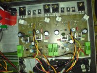
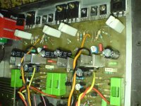
hey quasi and other diy'ers a few month's a go i build NMOS200
i found a thread in a romanian forum posted by alex mm
after browsing the net i found the original tread
WOOOWWW maaan there a over 3600 posts
what can i say this amplifier realy BLOW my speakers
the rails of NMOS200 is +/-32Vcc but the sound is so clear
now i wanna build NMOS350 version whit the rail of +/-85v
thank you Quasi for sharing this nice amp
sorry for my poor english
here some pics
Attachments
hey quasi and other diy'ers a few month's a go i build NMOS200
i found a thread in a romanian forum posted by alex mm
after browsing the net i found the original tread
WOOOWWW maaan there a over 3600 posts
what can i say this amplifier realy BLOW my speakers
the rails of NMOS200 is +/-32Vcc but the sound is so clear
now i wanna build NMOS350 version whit the rail of +/-85v
thank you Quasi for sharing this nice amp
sorry for my poor english
here some pics
for the output which transistor u use and thermal track transistor.
how do u adjust the bias?
can u share the romanian web u find.
can u share ur pcb layout.
Last edited:
i use irfp240 for output stage and bd139 for termal track
for adjusting bias i use a normal digital ampermeter in series with +v rail
(i know it was better to set bias with 100ohm /5w and 10ohm resistor as quasi sugested in his web site http://sites.google.com/site/quasisdiyaudiosite/home)
first befor powering up i set vr2 cursor to R13 i use a jumper in input
then powering up
i set ampermeter to 250mA and then adjust vr2 to get 50mA
after that adjust offset to les 10mV (i don't known exact value because it was a few month ago)
the amp is still working even whit low v rail of +/-32v
i use it with 8 ohm speakers and sensitivity (1w/1m): 90 dB
and i think i got about of 50w because of low v rail
but it sounds very loud and clear to (i think it's because of the sensitivity of the speaker)
romanian forum is Forumul electronistilor • Prima pagin?
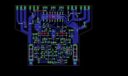
this is the PCB i use
you must open the files with EAGLE
when i print this i forgot to disable the mirror option that's why some resistor apear to cross other resistors
after i did those modifications whit no exageration the board (2xNMOS200 on single board) works for the first time i power up
i use press n' peel metod to create pcb
Attachments
i use irfp240 for output stage and bd139 for termal track
for adjusting bias i use a normal digital ampermeter in series with +v rail
(i know it was better to set bias with 100ohm /5w and 10ohm resistor as quasi sugested in his web site http://sites.google.com/site/quasisdiyaudiosite/home)
first befor powering up i set vr2 cursor to R13 i use a jumper in input
then powering up
i set ampermeter to 250mA and then adjust vr2 to get 50mA
after that adjust offset to les 10mV (i don't known exact value because it was a few month ago)
the amp is still working even whit low v rail of +/-32v
i use it with 8 ohm speakers and sensitivity (1w/1m): 90 dB
and i think i got about of 50w because of low v rail
but it sounds very loud and clear to (i think it's because of the sensitivity of the speaker)
romanian forum is Forumul electronistilor • Prima pagin?
for thermal tracking is it bc546 pins and bd139 pins are same.
bd139 is the same as all To126 pin out (ecb). This is exact reverse of To220 pin out (bce).
The bc5xx pin out is cbe.
Not the same.
As far as I know all bjt power devices have collector as the middle pin.
All Vfet power devices have drain as middle pin.
All latfet power devices have source as middle pin.
The bc5xx pin out is cbe.
Not the same.
As far as I know all bjt power devices have collector as the middle pin.
All Vfet power devices have drain as middle pin.
All latfet power devices have source as middle pin.
hey everybody
what do you think about this version of nmos200 pcb whit 2 pairs of irfp?
if somebody wants this version of scematic pcb just let me known
did u check this amp. how many watts and what is transformer voltage?
is your nmos200 transistor getting very hot?
this schematic you see here is the one i use and posted here http://www.diyaudio.com/forums/solid-state/43331-power-amp-under-development-370.html#post2508414 whit one pair irfp
basically is the original nmos200 whit one more pair of irfp
i do not see why this may not work
i think the power whit 2 pairs of irfp is around 80w 8 ohm (i think)
somebody correct me if i'm wrong
the transformer voltage should not exceed +/-50V as quasi said
but if you want to increase rail voltage more then +/-50 you may need to change T1, T5 to 2sc1845 and R7 (10K) to 18K or to be sure check nmos350/500 schematic for modifications
this schematic you see here is the one i use and posted here http://www.diyaudio.com/forums/solid-state/43331-power-amp-under-development-370.html#post2508414 whit one pair irfp
basically is the original nmos200 whit one more pair of irfp
i do not see why this may not work
i think the power whit 2 pairs of irfp is around 80w 8 ohm (i think)
somebody correct me if i'm wrong
the transformer voltage should not exceed +/-50V as quasi said
but if you want to increase rail voltage more then +/-50 you may need to change T1, T5 to 2sc1845 and R7 (10K) to 18K or to be sure check nmos350/500 schematic for modifications
in quasi website one pair output gives 200w into 4ohm.
why your 2 pairs output deliver 80w into 8ohm.
why is low wattage of yous?
+-50Vdc (from a 35+35Vac transformer) limits the maximum output voltage to ~38Vpk with a Source Follower output stage. This gives ~90W into 8r0.why is low wattage of your amplifier?
80W (35.8Vpk) into 8ohm speaker seems very normal for a mosFET amplifier as a continuous maximum rating.
It might be able to give as much as 42Vpk as a transient peak capability, if the duty cycle is low enough.
Why do you think it should be any different?
Last edited:
hey everybody
what do you think about this version of nmos200 pcb whit 2 pairs of irfp?
if somebody wants this version of scematic pcb just let me known
is it irfp260 or 240 best?
- Home
- Amplifiers
- Solid State
- Power amp under development